background image

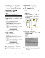
6. HDCP(High-Bandwidth Digital 

Contents Protection) Download

HDCP download process is deleted in H6 models
In H6 models, it is usimg the EEPROM masking HDCP Key

7. Manual ADC Adjustment 

(Component 1, RGB) 

[Caution]

- Do not connect external input cable
- Adjustment result is applied to SET On/Off later.

*  Adjustment  is  done  using  internal  ADC,  so  input  signal  is  not

necessary.

7-1. COMPONENT ADC (SD / HD) 

(1) Convert to Component1 input source.
(2) Press ADJ key on R/C for adjustment.
(3) Enter Password number. The value of Password is “0 0 0

0”.

(4) Select “0. ADC calibration” by using 

D

/

E

(CH +/-) and press

ENTER(

V

).

(5)  Start  ADC  adjustment  by  using 

F

/

G

(VOL  +/-)  or  press

ENTER(

V

).

(6) ADC adjustment is executed automatically .

When ADC adjustment is finished, this OSD appear.

7-2. RGB input ADC

Auto RGB Gain/Offset Adjustment

(1) Convert to PC in Input-source
(2) Press ADJ key on R/C for adjustment.
(3) Enter Password number. The value of Password is “0 0 0

0”.

(4) Select “0. ADC calibration” by using 

D

/

E

(CH +/-) and press

ENTER(

V

).

(5)  Start  ADC  adjustment  by  using 

F

/

G

(VOL  +/-)  or  press

ENTER(

V

).

(6) ADC adjustment is executed automatically .

When ADC adjustment is finished, this OSD appear.

Notice :

After All mode check, set the Speaker Volume “0”.

Caution 

: Don’t Press the Power Key on Remote Controller.

Just AC Power Off. ( Not DC off )

Notice :

From this sentence, All working is mass production.

8. POWER PCB Assy Voltage

Adjustment

(Vs voltage Adjustment)

8-1. Test Equipment:

D.M.M 1EA

8-2. Connection Diagram for Measuring

Refer to (Fig. 4)

8-3. Adjustment Method 

(1) Vs Adjustment

1)  Connect  +  terminal  of  D.  M..M.  to  Vs  pin  of  P702,

connect -terminal to GND pin of P702.

2)  After  turning  VR901,  voltage  of  D.M.M  adjustment  as

same as Vs voltage which on label of panel right/top  (
deviation ; ±0.5V)

8-4. Adjustment of Area option.

(1) Area  Option  Adjustment  following  BOM

(Including SKD models)

Tool Option
Area Option
Option 1
Option 2
Option 3 ( Available for EU & Non EU model )

* Profile : Must  be  changed  the  option  value  because  being

different  with  some  setting  value  depend  on  module,
inch and market

- 11 -

LGE Internal Use Only

Copyright ©2009 LG Electronics. Inc. All right reserved. 
Only for training and service purposes

RF input

NO SIGNAL or White noise

AV / Component / RGB input

NO SIGNAL

(Fig. 4)

..

Содержание 42PQ10R

Страница 1: ...S READ THE SAFETY PRECAUTIONS IN THIS MANUAL CHASSIS PP91C MODEL 42PQ10R 42PQ10R MB North Latin America http aic lgservice com Europe Africa http eic lgservice com Asia Oceania http biz lgservice com Internal Use Only P NO MFL62181703 0909 REV00 Printed in Korea ...

Страница 2: ...Only Copyright 2009 LG Electronics Inc All right reserved Only for training and service purposes CONTENTS CONTENTS 2 SAFETY PRECAUTIONS 3 SPECIFICATION 4 ADJUSTMENT INSTRUCTION 7 BLOCK DIAGRAM 15 EXPLODED VIEW 16 SVC SHEET ...

Страница 3: ... s Neck Leakage Current Cold Check Antenna Cold Check With the instrument AC plug removed from AC source connect an electrical jumper across the two AC plug prongs Place the AC switch in the on position connect one lead of ohm meter to the AC plug prongs tied together and touch other ohm meter lead in turn to each exposed metallic parts such as antenna terminals phone jacks etc If the exposed meta...

Страница 4: ... specification by part number in accordance with SBOM 5 The receiver must be operated for about 20 minutes prior to the adjustment V Test Method 1 Performance LGE TV test method followed 2 Demanded other specification Safety CE IEC specification EMC CE IEC V Module Specification 1 42 XGA Chassis PP91C 42PQ10R MB Central and South America LG Model Name Market Brand Model Name 42PQ10R MB Remark Safe...

Страница 5: ...nput 1EA PQ10R rear 1EA 6 AV Output 1EA NTSC PAL M N Rear 1EA You can select Variable OUT or MNT OUT PQ10R Not support 7 Component Input 2EA Y Cb Cr Y Pb Pr Component Input 1EA PQ10R rear 1EA 8 RGB Input 1EA RGB PC PQ10R Not support 9 HDMI Input 2EA 1ea HDMI DTV Only PCM MODE Rear HDMI 1 Only for PQ10R 2ea Rear HDMI 2 Only for PQ30R 3ea Side HDMI 1 Rear HDMI 2 10 Audio Input 2EA AV 1EA Component 1...

Страница 6: ...id 3 Brightness uniformity 10 0 10 85IRE Full White Pattern Picture Mode Vivid White X 0 270 0 285 0 300 White 216 level pattern Y 0 278 0 293 0 308 Red Green Blue 255 level pattern Red X 0 635 0 640 4 Color Y 0 318 0 330 0 340 coordinate Green X 0 242 0 300 0 305 Y 0 595 0 600 Blue X 0 150 0 158 Y 0 060 0 070 5 Contrast ratio at dark room 100 000 1 1 000 000 1 White 1 100 White Window Pattern Pea...

Страница 7: ...minutes prior to the adjustment when module is in the circumstance of over 15 In case of keeping module is in the circumstance of 0 C it should be placed in the circumstance of above 15 C for 2 hours In case of keeping module is in the circumstance of below 20 C it should be placed in the circumstance of above 15 C for 3 hours 3 S W Program Download 3 1 Profile This is for downloading the s w to t...

Страница 8: ...be bigger than downloaded version of main B D 1 Using Power ON button of the control R C Power on TV 2 Insert the USB memory stick to the SET 3 Display USB loding message then push the Exit Key of control R C 4 Push the MENU Key and move the cusor OPTION of OSD Fig 1 Caution Don t push the OK key Just cusor is on the OPTION menu 5 Push the 7 key of control R C continuously Then Display TV Software...

Страница 9: ...When you adjust tool option don t connect HDMI or D sub cable If you connect some cable EDID D L process will be failed 6 Adjustment method Before PCBA check have to change the Tool option and Area option About PDP After done all adjustments Press IN START button and compare Tool option and Area option value with its BOM if it is correctly same then Change RF mode and then unplug the AC cable If i...

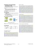
Страница 10: ...quipment 1 Adjusting PC with S W for writing EDID Data S W EDID TESTER Ver 2 5 2 A Jig for EDID Download 3 Cable Serial 9Pin or USB to D sub 15Pin cable D sub 15Pin cable DVI to HDMI cable 5 3 Connection Structure Caution Never connect HDMI D SUB Cable at the same time 5 4 EDID Data O XGA EDID DATA 42 inch Analog RGB 128bytes HDMI 1 256bytes HDMI 2 256bytes HDMI 3 256bytes SIDE HDMI HDMI 3 10 LGE ...

Страница 11: ...ent by using F G VOL or press ENTER V 6 ADC adjustment is executed automatically When ADC adjustment is finished this OSD appear Notice After All mode check set the Speaker Volume 0 Caution Don t Press the Power Key on Remote Controller Just AC Power Off Not DC off Notice From this sentence All working is mass production 8 POWER PCB Assy Voltage Adjustment Vs voltage Adjustment 8 1 Test Equipment ...

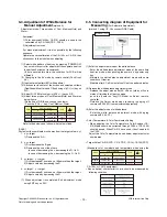
Страница 12: ...tor MSPG 925FA etc Before white balance press the ADJ key and select third row like Fig 5 To enter White balance mode Enter Password Number 0 0 0 0 and select third row Caution System control Host should be DDC for adjustment 6 Adjust W B DATA for all CSM choose COPY ALL 9 3 Connecting Diagram of Equipment for Measuring For Automatic Adjustment Method 2 using RS 232C You connect RS 232C Cable 1 En...

Страница 13: ...adjustment mode using EXIT key on R C 9 5 Connecting diagram of Equipment for Measuring For Automatic Adjustment method 1 using IIC You connect RGB Cable 1 Enter the adjustment mode of the white balance Enter the white balance adjustment mode at the same time heat run mode when pushing the power on by power only key Maintain the white balance adjustment mode with same condition of Heat run Maintai...

Страница 14: ...14 LGE Internal Use Only Copyright 2009 LG Electronics Inc All right reserved Only for training and service purposes O DDC Adjustment Command Set R G B GAIN max value C0 Adjustment Adjustment Adjustment ...

Страница 15: ... 15 LGE Internal Use Only Copyright 2009 LG Electronics Inc All right reserved Only for training and service purposes BLOCK DIAGRAM ...

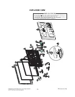
Страница 16: ...parts in this chassis have special safety related characteristics These parts are identified by in the Schematic Diagram and EXPLODED VIEW It is essential that these special safety parts should be replaced with the same components as recommended in this manual to prevent X RADIATION Shock Fire or other Hazards Do not modify the original design without permission of manufacturer IMPORTANT SAFETY NO...

Страница 17: ......

Страница 18: ......

Страница 19: ......

Страница 20: ......

Страница 21: ......

Страница 22: ......

Страница 23: ......

Страница 24: ......

Страница 25: ......

Отзывы: