- 22 -
LGE Internal Use Only
Copyright©2007 LG Electronics. Inc. All right reserved.
Only for training and service purposes
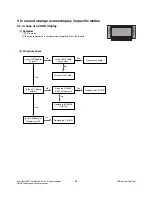
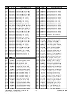
3. Protect Mode
(1) Symptom
1) After lighting up once, it does not discharge
minutely from module.
2) The rely falls.(there is an audible “click”)
3) The color of the front LED turns from green to red.
(2) Procedure check
Is the Power Board
normal ?
Replace the Power Board.
Is the output Low/High voltage normal
except for Stand-by 5V?
Yes
No
No
Is the each connector
normal?
Replace the connector.
Replace the
Y-Board.
After connecting each connector do
they operate normally?
Yes
No
Yes
Is the Ctrl Board
normal?
Replace the
X-Board.
Is the output voltage normal after
removing P1, 2, 4, 9, 10 connectors of
the Ctrl-B/D?
Yes
No
Yes
Is the Y-Board
normal?
Is the output voltage
normal after removing
P103 connector of
Y-B/D?
Is the appropriate Fuse(FS101,FS102)
on the Y-B/D normal?(Replace if open)
Yes
No
Yes
Yes
Replace the
Z-Board.
Is the Z-Board
normal?
Is the output voltage
normal after removing
P1 connector of
Z-B/D?
Is the appropriate Fuse (FS1, FS2) on
Z-B/D? (replace if open)
Yes
No
Yes
Is the X- Board
normal?
Is the output voltage normal after
removing P1, 2, 3, 4, 5 connectors of
the X-B/D?
If the output voltage is normal after removing
the P1, P2, P3 : Replace the right X-B/D
If the output voltage is normal after removing
the P4, P5 : Replace the left X-B/D
Yes
No
Yes
Is the
VSC Board normal?
Is the output voltage normal after
removing P900, P901 of VSC Board?
After a COF crisis for each board, check the normal operation. For normal operation,
corresponding COF failure means the module should be relaced.
If it operates normally after removing the
P900, P901 : Replace the VSC Board
Yes
No
Is the COF of X, Y, Z
normal ?
No
Yes
Yes
Содержание 42PC35
Страница 53: ...Oct 2007 Printed in Korea P NO MFL38562712 ...


