- 21 -
No image
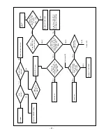
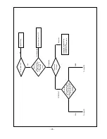
Power
Error
Attach the input cable(s)
RF/AV/IDTV input
Push the POWER ON key
Correct them
Replace IC1 AN15865
Check Tuner, SCART1/2
Front AV or Digital board
Accordingly w.r.t the Mode.
Is the
Set ON?
Power Error
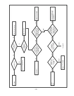
Replace IC1 AN15865
Is the input cable
attached?
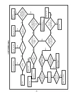
What is
the input signal
mode?
Check main
CVBS at R303
Check
Secondary CVBS
at R434 (for PiP)
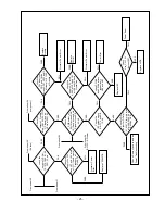
Check 9V
Across L401and
at pin 3 of IC100
5V across
L404 , L402
Check 9V
Across L401and
at pin 3 of IC100
5V across
L404,L402
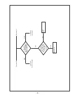
Check the
input video signal
at pin 48, 50, 52, 54, 60
of AN15865 For RF,
AV1/2/3, IDTV
Resp.
Check the
Condition of all
Connectors, wafers, I2C
In corresponding
Signal flow
Yes
NO
Yes
FAIL
PASS
FAIL
FAIL
PASS
PASS
PASS
FAIL
FAIL
FAIL
PASS
PASS
NO
To sheet 25
From sheet 26
Содержание 37LP1DA-ZA
Страница 32: ... 33 EXPLODED VIEW 010 020 040 160 180 210 120 130 150 151 060 080 090 170 100 110 030 050 140 070 190 200 ...
Страница 57: ......
Страница 58: ......
Страница 59: ......
Страница 60: ......
Страница 61: ...Fer 2006 Printed in Korea P NO ...


