background image

- 4 -

CAUTION: Before servicing receivers covered by this service
manual and its supplements and addenda, read and follow the

SAFETY PRECAUTIONS

on page 3 of this publication.

NOTE: 

If unforeseen circumstances create conflict between the

following servicing precautions and any of the safety precautions on
page 3 of this publication, always follow the safety precautions.
Remember: Safety First.

General Servicing Precautions
1.  Always unplug the receiver AC power cord from the AC power

source before;
a.  Removing or reinstalling any component, circuit board

module or any other receiver assembly.

b.  Disconnecting or reconnecting any receiver electrical plug or

other electrical connection.

c. Connecting a test substitute in parallel with an electrolytic

capacitor in the receiver.

CAUTION:

A wrong part substitution or incorrect polarity

installation of electrolytic capacitors may result in an
explosion hazard.

2.  Test high voltage only by measuring it with an appropriate high

voltage meter or other voltage measuring device (DVM,
FETVOM, etc) equipped with a suitable high voltage probe.
Do not test high voltage by "drawing an arc".

3.  Do not spray chemicals on or near this receiver or any of its

assemblies.

4. Unless specified otherwise in this service manual, clean

electrical contacts only by applying the following mixture to the
contacts with a pipe cleaner, cotton-tipped stick or comparable
non-abrasive applicator; 10% (by volume) Acetone and 90% (by
volume) isopropyl alcohol (90%-99% strength)

CAUTION:

This is a flammable mixture.

Unless specified otherwise in this service manual, lubrication of
contacts in not required.

5.  Do not defeat any plug/socket B+ voltage interlocks with which

receivers covered by this service manual might be equipped.

6.  Do not apply AC power to this instrument and/or any of its

electrical assemblies unless all solid-state device heat sinks are
correctly installed.

7.  Always connect the test receiver ground lead to the receiver

chassis ground before connecting the test receiver positive
lead.
Always remove the test receiver ground lead last.

8. 

Use with this receiver only the test fixtures specified in this
service manual.

CAUTION:

Do not connect the test fixture ground strap to any

heat sink in this receiver.

Electrostatically Sensitive (ES) Devices

Some semiconductor (solid-state) devices can be damaged easily
by static electricity. Such components commonly are called

Electrostatically Sensitive (ES) Devices.

Examples of typical ES

devices are integrated circuits and some field-effect transistors and
semiconductor "chip" components. The following techniques
should be used to help reduce the incidence of component
damage caused by static by static electricity.
1.  Immediately before handling any semiconductor component or

semiconductor-equipped assembly, drain off any electrostatic
charge on your body by touching a known earth ground.
Alternatively, obtain and wear a commercially available
discharging wrist strap device, which should be removed to

prevent potential shock reasons prior to applying power to the
unit under test.

2.  After removing an electrical assembly equipped with ES

devices, place the assembly on a conductive surface such as
aluminum foil, to prevent electrostatic charge buildup or
exposure of the assembly.

3.  Use only a grounded-tip soldering iron to solder or unsolder ES

devices.

4. Use only an anti-static type solder removal device. Some solder

removal devices not classified as "anti-static" can generate
electrical charges sufficient to damage ES devices.

5.  Do not use freon-propelled chemicals. These can generate

electrical charges sufficient to damage ES devices.

6.  Do not remove a replacement ES device from its protective

package until immediately before you are ready to install it.
(Most replacement ES devices are packaged with leads
electrically shorted together by conductive foam, aluminum foil
or comparable conductive material).

7.  Immediately before removing the protective material from the

leads of a replacement ES device, touch the protective material
to the chassis or circuit assembly into which the device will be
installed.

CAUTION: 

Be sure no power is applied to the chassis or circuit,

and observe all other safety precautions.

8. Minimize bodily motions when handling unpackaged

replacement ES devices. (Otherwise harmless motion such as
the brushing together of your clothes fabric or the lifting  of your
foot from a carpeted floor can generate static electricity
sufficient to damage an ES device.)

General Soldering Guidelines
1.  Use a grounded-tip, low-wattage soldering iron and appropriate

tip size and shape that will maintain tip temperature within the
range or 500

o

F to 600

o

F.

2.  Use an appropriate gauge of RMA resin-core solder composed

of 60 parts tin/40 parts lead.

3.  Keep the soldering iron tip clean and well tinned.
4.  Thoroughly clean the surfaces to be soldered. Use a mall wire-

bristle (0.5 inch, or 1.25cm) brush with a metal handle.
Do not use freon-propelled spray-on cleaners.

5.  Use the following unsoldering technique

a.  Allow the soldering iron tip to reach normal temperature.

(500

o

F to 600

o

F)

b.  Heat the component lead until the solder melts.
c.  Quickly draw the melted solder with an anti-static, suction-

type solder removal device or with solder braid.
CAUTION: Work quickly to avoid overheating the circuit
borad printed foil.

6.  Use the following soldering technique.

a.  Allow the soldering iron tip to reach a normal temperature

(500

o

F to 600

o

F)

b.  First, hold the soldering iron tip and solder the strand against

the component lead until the solder melts.

c.

Quickly move the soldering iron tip to the junction of the

component lead and the printed circuit foil, and hold it there
only until the solder flows onto and around both the
component lead and the foil.

CAUTION:

Work quickly to avoid overheating the circuit

board printed foil.

d.

Closely inspect the solder area and remove any excess or

splashed solder with a small wire-bristle brush.

SERVICING PRECAUTIONS

Содержание 20HIZ20

Страница 1: ...R LCD TV SERVICE MANUAL CAUTION BEFORE SERVICING THE CHASSIS READ THE SAFETY PRECAUTIONS IN THIS MANUAL CHASSIS LP69F MODEL 20HIZ20 20LS1RH ZK website http biz LGservice com ...

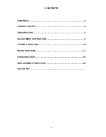
Страница 2: ... 2 CONTENTS CONTENTS 2 PRODUCT SAFETY 3 SPECIFICATION 6 ADJUSTMENT INSTRUCTION 9 TROUBLE SHOOTING 13 BLOCK DIAGRAM 17 EXPLODED VIEW 20 REPLACEMENT PARTS LIST 22 SVC SHEET ...

Страница 3: ...Current Cold Check Antenna Cold Check With the instrument AC plug removed from AC source connect an electrical jumper across the two AC plug prongs Place the AC switch in the on position connect one lead of ohm meter to the AC plug prongs tied together and touch other ohm meter lead in turn to each exposed metallic parts such as antenna terminals phone jacks etc If the exposed metallic part has a ...

Страница 4: ...y obtain and wear a commercially available discharging wrist strap device which should be removed to prevent potential shock reasons prior to applying power to the unit under test 2 After removing an electrical assembly equipped with ES devices place the assembly on a conductive surface such as aluminum foil to prevent electrostatic charge buildup or exposure of the assembly 3 Use only a grounded ...

Страница 5: ...not shiny reheat them and if necessary apply additional solder Fuse and Conventional Resistor Removal Replacement 1 Clip each fuse or resistor lead at top of the circuit board hollow stake 2 Securely crimp the leads of replacement component around notch at stake top 3 Solder the connections CAUTION Maintain original spacing between the replaced component and adjacent components and the circuit boa...

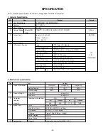
Страница 6: ... colors P N Size mm 432 W x 331 5 H x 25 0 D EAJ30338001 Surface Treatment Hard Coating 3H Anti Glare treatment of the front polarizer Operating Mode Normally Black Back light Unit 6 CCFL 6 lamps R T Typ 25ms R T 12ms F T 13ms No 1 Product Dimension Width W Length D Height H Before Packing 573 2 189 7 453 5 After Packing 635 177 470 2 Product Weight Only SET 6 9kg LPL With BOX 8 7kg LPL 3 Containe...

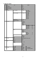
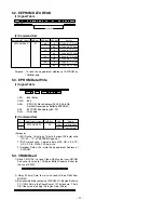
Страница 7: ...Name Programme Edit To set Favourite Programme Off 7 PICTURE PSM Dynamic Standard Mild Game User Contrast 100 Brightness 50 Colour 60 Sharpness 50 Tint 0 CSM Cool Normal Warm User Red 0 Green 0 Blue 0 XD Auo Manual Reset To set 8 SOUND SSM Flat Music Movie Sports User AVL Off Balance 0 9 TIME Time Off time Off On time Pr 1 Vol 30 Off Auto sleep Off 10 SPECIAL Language English 16 Language Country O...

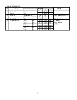
Страница 8: ...e cd m2 250 320 PSM Dynamic CSM Cool White luminance uniformity 75 80 3 Contrast Ratio CR 500 600 All white All black 4 CIE Color Coordinates White Wx 0 298 0 313 0 328 In AV input Warm Wy 0 314 0 329 0 344 PSM Dynamic White Wx 0 268 0 283 0 298 85 IRE Normal Wy 0 283 0 298 0 313 White Wx 0 259 0 274 0 289 Cool Wy 0 271 0 286 0 301 ...

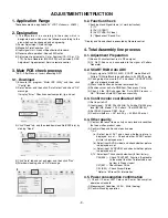
Страница 9: ... 2 SCART RGB Auto ADC 1 Apply signal of MSPG 1025D SCART mode Model 2 Pattern 19 White Black top and bottom with SCART cable 2 Change input source to AV1 and check if SCART RGB signal is properly displayed 3 Press Instart button on service remote control 4 Position cursor on Auto RGB item Then press Vol up 5 Check if the OSD changes like Auto RGB Process OK OK means Auto ADC done successfully 4 3 ...

Страница 10: ... Denmark England Estonia Finland France Germany Greece Hungary Italy Latvia Netherlands Norway Poland Portugal Rumania Russia Serbia Slovakia Slovenia Spain Sweden Switzerland Turkey Arab Hebrew Others 0 2 Hour off option OFF 1 2 Hour off option ON 0 EEPROM Write Protection On 1 EEPROM Write Protection Off VAL 00 00 00 00 data 00 00 100 00 100 00 100 00 100 00 FF 00 FF 00 FF 00 7F 00 7F 00 7F 00 3...

Страница 11: ...for the use of EDID 2 Delay 500ms Time to wait and read vZideo RAM from MICOM 3 Be transmitted the contents of MICOM s 128 bytes Buffer to PC 128th Data is the CheckSum of 127 bytes data That s OK if the value of adding 128 bytes Data is Zero 11 ST OP A A A A A 50 6E 03 CMD ADH 84 n ST ART ADL A CS A A Data_1 A Data_n A No 1 2 Adjustment contents EEPROM WRITE CMD hex E8 LEN 94 84 n Details 16 Byte...

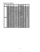
Страница 12: ...NICAM DUAL S 07 PR 12 591 25 PAL L Colorbar NICAM STEREO C 48 PR 13 791 25 SECAM DK Colorbar MUSIC C61 PR 14 175 25 PAL B PHILIPS A2 STEREO PR 15 711 25 PAL G Colorbar MONO PR 16 631 25 PAL I Colorbar NICAM STEREO TOP PR 17 93 25 SECAM D PHILIPS A2 DUAL FLOF PR 18 62 25 PAL B RED Circle Cross A2 STEREO FLOF PR 19 551 25 PAL G Colorbar A2 DUAL PR 20 471 25 PAL I Colorbar NICAM STEREO FLOF PR 21 687...

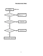
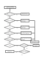
Страница 13: ...wer LED indicator off Check short of main B D or Change Lips Change Q903 Change LED Assy Check 15V or 5V of Lips Check Input Output of Q903 Check LED Assy Check S W update connector P281 Fail Fail Fail Pass Pass Pass A Process ...

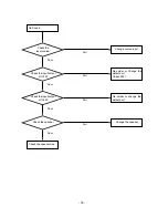
Страница 14: ...eck Inverter on Check Inverter connector Check IC900 IC901 IC906 IC907 IC909 IC910 output voltage Repeat A PROCESS Fail Change Lips Fail Change Defect IC Fail Check input signal cabel Fail Check panel link cable Pass Pass Pass B Process Pass ...

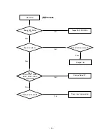
Страница 15: ...Yes Check L822 R124 R831 of video signal Repeat A Process Pass No Pass If RGB of SCART Yes Check R280 R281 R282 R110 R112 R114 of video singal No Yes If If CVBS of SCART Yes Check L205 R210 R121 of video signal Check Signal Input jack Check IC911 906 and Lips Change Tuner No If Tuner Yes Yes 5V_Tuner is On Video valid on tuner Pin 13 Yes ...

Страница 16: ...input Check the input source Fail Pass Re solder or Change the defect part Check X301 Check the input output of IC100 Fail Pass Re solder or change the defect part Check the input output of IC400 Fail Pass Change the speaker Check the speaker Fail Pass ...

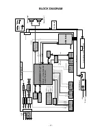
Страница 17: ...32C LED IR Control Power Video Audio Data Address Data CLK DQM W EZ CASZ RASZ MX232A TPA6011A Audio amp RS232C M12L16161A 5TG SDRAM CVBS Tuner CVBS Tuner SCL SDA SCL SDA Rx Tx Rx Tx 12C SDA SCL 8 ohm 1W Mono BTL output SIF_OUT CVBS OUT LGE9689AD LF 1 Scaler Video Decoder Audio Processor SCART Jack D Sub Service CS4352 DAC 3 3V 12V Regulator Regulator Regulator Regulator Regulator 5V 1 8V LED IR Bo...

Страница 18: ...d DC volume control curve Audio Video Decoder Scaler This block is composed of LGE9655 and peripheral devices 1 Video Decoder This Block Selects input Video signals like CVBS Y C SCART RGB and output LVDS TTL signal through Scaler On decoding We can control signal like Contrast Brightness Sharpness Color tint signals including Adaptive Comb Filter 2 Audio Decoder This block analyzes audio input si...

Страница 19: ... 19 MEMO ...

Страница 20: ... 20 EXPLODED VIEW 300 121 121 120 120 570 591 590 200 210 580 210 520 411 413 440 441 430 530 412 400 434 431 432 433 550 410 ...

Страница 21: ...late PRESS SBHG1 A 0 8T SUPPORTER SBHG A 20LS1R METAL SUPPORT BRACKET 430 AAN30637902 Base Assembly STAND 20LS1R CL81 BASE _Metal AAN30637911 Base Assembly STAND 23LS2R LP69B 23LS2 BASE _METAL CSKD 431 AJJ30377302 Supporter Assembly 20LS1R HINGE ASS Y 432 MCK30558101 Cover MOLD ABS 380 LS1R ABS HF 380 LS1R COVER HINGE BODY 433 MCK30558601 Cover MOLD ABS 380 20LS1R ABS HF 380 HINGE COVER L 434 MCK3...

Страница 22: ...0V 150MA Q903 EBK32753101 SI4925BDY P CHANNEL MOSFET 30V Q904 0TR390409AE KST3904 NPN 6V 60V 40V 200MA 50NA 1 D100 0DSGD00038A 1N4148W 1 25V 100V 150MA 2A 4NSEC 4 D400 0DS181009AA KDS181 1 2V 85V 300MA 2A 4NSEC 150M D401 0DS181009AA KDS181 1 2V 85V 300MA 2A 4NSEC 150M D402 0DS181009AA KDS181 1 2V 85V 300MA 2A 4NSEC 150M ZD200 0DZ560009DA UDZS5 6B 5 6V 5 49TO5 73V 60OHM 200 ZD201 0DZ560009DA UDZS5 ...

Страница 23: ... 0CK104CK56A 0603B104K500CT 100nF 10 50V X7R 5 C172 0CK104CK56A 0603B104K500CT 100nF 10 50V X7R 5 C173 0CK104CK56A 0603B104K500CT 100nF 10 50V X7R 5 C174 0CK104CK56A 0603B104K500CT 100nF 10 50V X7R 5 C175 0CK104CK56A 0603B104K500CT 100nF 10 50V X7R 5 C176 0CK104CK56A 0603B104K500CT 100nF 10 50V X7R 5 C177 0CE106SF6DC VMV106M016S0ANB010 10uF 20 16V C178 0CK104CK56A 0603B104K500CT 100nF 10 50V X7R 5...

Страница 24: ...0G 5 C822 0CC331CK41A C1608C0G1H331JT 330pF 5 50V C0G 5 C823 0CC331CK41A C1608C0G1H331JT 330pF 5 50V C0G 5 C860 0CH2474F566 0805B474K160CT 470nF 10 16V X7R 5 C861 0CK474DF51A C2012Y5P1C474KT 470nF 10 16V Y5P C862 0CK474DF51A C2012Y5P1C474KT 470nF 10 16V Y5P C863 0CK474DF51A C2012Y5P1C474KT 470nF 10 16V Y5P C865 0CE106WFKDC MVK4 0TP16VC10M 10uF 20 16V 16MA C880 0CC102CK41A C1608C0G1H102JT 1nF 5 50V...

Страница 25: ...HM 5 1 8W 2012 R R108 0RJ1000D677 MCR03EZPJ101 100OHM 5 1 10W 1608 R R109 0RH4701D622 MCR10EZHJ472 4 7KOHM 5 1 8W 2012 R R110 0RH4702D622 MCR10EZHJ473 47KOHM 5 1 8W 2012 R R110 0RJ0472D677 MCR03EZPJ470 47OHM 5 1 10W 1608 R R111 0RH1000D622 MCR10EZHJ101 100OHM 5 1 8W 2012 R R111 0RJ0472D677 MCR03EZPJ470 47OHM 5 1 10W 1608 R R112 0RH1000D622 MCR10EZHJ101 100OHM 5 1 8W 2012 R R112 0RJ0472D677 MCR03EZ...

Страница 26: ...01D677 MCR03EZPJ102 1KOHM 5 1 10W 1608 R R3006 0RJ1001D677 MCR03EZPJ102 1KOHM 5 1 10W 1608 R R3007 0RJ1001D677 MCR03EZPJ102 1KOHM 5 1 10W 1608 R R3204 0RJ4701D677 MCR03EZPJ472 4 7KOHM 5 1 10W 1608 R4000 0RN6801F409 RN 96T1F6K80 6 8KOHM 1 1 6W 3 2X1 R4001 0RN2201F409 RN 96T1F2K20 2 2KOHM 1 1 6W 3 2X1 R4002 0RN1001F409 RN 96T1F1K00 1KOHM 1 1 6W 3 2X1 8M R4003 0RN6801F409 RN 96T1F6K80 6 8KOHM 1 1 6W ...

Страница 27: ...012 301JT H 1mm 300OHM 2X1 2 L251 6210TCE001G HH 1M3216 501JT 500OHM 3 2X1 6X1 3M L261 6210TCE001H HB 1T2012 301JT H 1mm 300OHM 2X1 2 L262 6210TCE001H HB 1T2012 301JT H 1mm 300OHM 2X1 2 L270 6210TCE001G HH 1M3216 501JT 500OHM 3 2X1 6X1 3M L271 6210TCE001H HB 1T2012 301JT H 1mm 300OHM 2X1 2 L400 6210TCE001G HH 1M3216 501JT 500OHM 3 2X1 6X1 3M L405 6210TCE001G HH 1M3216 501JT 500OHM 3 2X1 6X1 3M L40...

Страница 28: ......

Страница 29: ......

Страница 30: ...Jan 2007 Printed in Korea P NO MFL35928001 ...

Отзывы: