background image

- 18 -

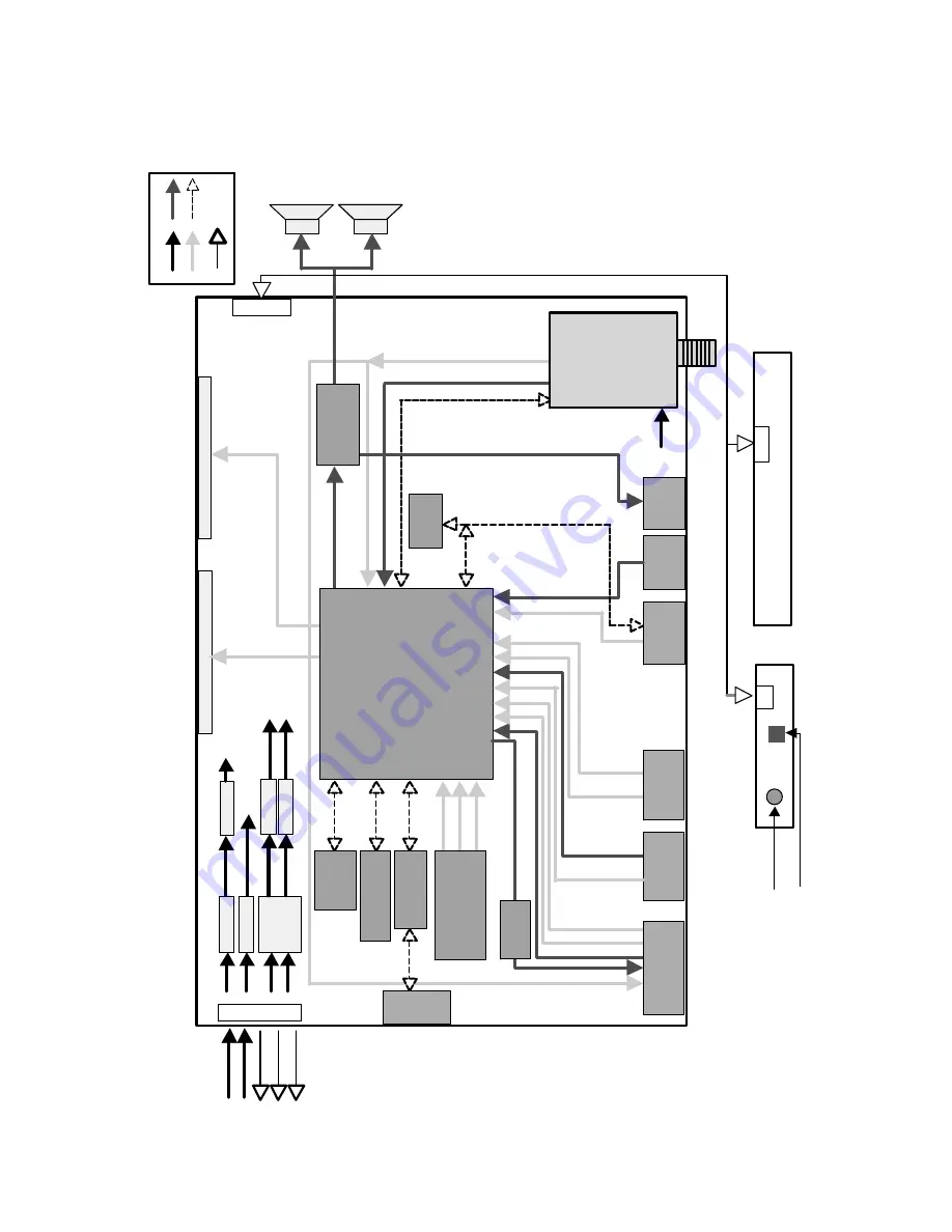
BLOCK DIAGRAM

IR

 d

e

te

ct

or

5V

LV

D

S

 M

O

D

U

L

E

M

X

25L

400

5A

(S

e

ri

al

 F

lash

)

Co

n

tr

o

l B

o

a

rd

(T

a

c

t S

w

it

c

h

)

LE

D

S

p

eaker L

e

ft

S

p

eaker R

ight

TTL M

O

D

U

L

E

15V

5V

15V

12V

_

P

a

ne

l

5V

5V

15V

LIP

S

RGB i

n

A udi

o out

A udi

o in

CVBS

 in

Vide

o in

A udi

o in

Y in

C in

CVBS

 ou

t

C

ont

ro

l i

n

/out

EE

P

R

O

M

(24C

64)

CV

BS

Jack

S

-V

ide

o

Jack

Ste

re

o

-I

n

(Opt

io

n)

H/

P

Out

put

LE

D / IR

 / Co

ntr

ol

Po

w

e

r

Vi

de

o

A

udi

o

Da

ta

A

ddr

e

ss

Da

ta

CL

K,

DQ

M

,

WE

Z

,C

A

S

Z

,R

A

S

Z

EE

P

R

O

M

(24C

02)

M

12L

1

616

1A

-5

T

G

(S

D

RAM

)

C

V

B

S

 Tune

r

C

V

B

S

 Tune

r

SC

L

/SD

A

SC

L

/SD

A

SC

L

/SD

A

SI

F

_

O

U

T

CV

BS

 O

U

T

M

S

T

9

6

585

(S

c

a

le

r +

 V

ideo D

e

c

oder

)

SC

A

R

T

Jack

D

-Su

b

(Opt

io

n)

RS-232C

(Option)

Rx

/T

x

C

S

4352

(D

A

C

)

3.

3V

12V

Re

gula

to

r

Re

gula

to

r

Re

gula

to

r

Re

gula

to

r

Re

gula

to

r

5V

1.

8V

LE

D

/IR

 B

oar

d

Co

nt

ro

l

M

X

232A

(R

S

-232C

)

ON

/O

F

F

PWM

_

D

IM

DI

M

_

C

T

L

YD

A

1

3

8

(A

udi

o a

m

p)

Rx

/T

x

F

E

T

 Swi

tch

(SI

4925B

D

Y

)

5V

12V

IF

_

V

id

e

o

Содержание 15LS1R SERIES

Страница 1: ...CE MANUAL CAUTION BEFORE SERVICING THE CHASSIS READ THE SAFETY PRECAUTIONS IN THIS MANUAL CHASSIS LP68A FACTORY MODEL 15LS1R ZK MODEL 15LS1R website http biz LGservice com e mail http www LGEservice com techsup html ...

Страница 2: ...TS CONTENTS 2 PRODUCT SAFETY 3 SERVICING PRECAUTIONS 4 SPECIFICATION 6 ADJUSTMENT INSTRUCTION 9 SERVICE REMOTE CONTROL 13 TROUBLE SHOOTING 14 BLOCK DIAGRAM 18 EXPLODED VIEW 20 REPLACEMENT PARTS LIST 22 SVC SHEET ...

Страница 3: ...Current Cold Check Antenna Cold Check With the instrument AC plug removed from AC source connect an electrical jumper across the two AC plug prongs Place the AC switch in the on position connect one lead of ohm meter to the AC plug prongs tied together and touch other ohm meter lead in turn to each exposed metallic parts such as antenna terminals phone jacks etc If the exposed metallic part has a ...

Страница 4: ...y obtain and wear a commercially available discharging wrist strap device which should be removed to prevent potential shock reasons prior to applying power to the unit under test 2 After removing an electrical assembly equipped with ES devices place the assembly on a conductive surface such as aluminum foil to prevent electrostatic charge buildup or exposure of the assembly 3 Use only a grounded ...

Страница 5: ...not shiny reheat them and if necessary apply additional solder Fuse and Conventional Resistor Removal Replacement 1 Clip each fuse or resistor lead at top of the circuit board hollow stake 2 Securely crimp the leads of replacement component around notch at stake top 3 Solder the connections CAUTION Maintain original spacing between the replaced component and adjacent components and the circuit boa...

Страница 6: ...Color Depth 6BIT WHITE FRC 16 2M colors P N Size mm 326 6 W x 253 5 H x 14 0 D 6304FCP009A Surface Treatment Anti Glare HAZE 3 Hard Coating 3H CLAA150XP03 Operating Mode Normally White TN Back light Unit 4 CCFL 4 lamps R T Typ R T 5ms F T 11ms Typ No 1 Product Dimension Width W Length D Height H Before Packing 463 3 166 3 353 5 With Stand After Packing 527 0 175 0 470 0 2 Product Weight Only SET 3...

Страница 7: ...ghtness 2 H Position V Position 3 Tracking Clock Phase 4 Auto Configure 5 Reset 4 Optical Characteristic No Item Specification Remark Min Tpy Max 1 Viewing Angle R L 75 75 85 85 CPT CR 10 U D 50 55 60 65 All white All black 2 Luminance Luminance CEN cd m2 250 300 100IRE 5P Uniformity 75 80 3 Contrast Ratio CR 3000 4 CIE Color Coordinates White Wx 0 268 0 283 0 298 In PC input Contrast Normal Wy 0 ...

Страница 8: ...e Manual Programme Programme Edit Favourite Programme None 7 PICTURE PSM Dynamic CSM Cool Reset 8 SOUND SSM Flat AVL Off Balance 0 9 TIME Time Off time Off On time Pr 1 Vol 30 Off Auto sleep Off 10 SPECIAL Language English 16 Language Country Others 30 Language Child Lock Off 11 Screen Auto config Manual config H V Position Clock Phase Auto configure value Reset ...

Страница 9: ...ash Memory 4 Click Read tab and then load download file XXXX bin by clicking Read 5 Click Auto tab and set as below and then click Run 6 After downloading check OK message 3 2 ADC Process 1 PC input ADC 1 Auto RG Gain Offset Adjustment a Convert to PC in Input source b Signal equipment displays Output Voltage 730 mVp p Impress Resolution XGA 1024 x 768 60Hz Pattern gray pattern that left right is ...

Страница 10: ...ormation 3 RGB Select input RGB and check whether picture is displayed or not 4 5 DPM operation confirmation 1 Check if Power LED Color and Power Consumption operate as standard 2 Set Input to RGB and connect D sub cable to set 3 Measurement Condition 230V 50Hz Analog 4 Confirm DPM operation at the state of screen without Signal 4 6 DDC EDID 1 Connect D sub Signal Cable to D Sub Connector 2 Write ...

Страница 11: ... Luminance adjustment Auto COLOR Adjustment 0 COOL 1 NORMAL 2 WARM 3 USER Factory mode off II_SW is 1 Input change to TV 0 TV 1 AV1 2 AV2 3 Component 4 RGB 5 DVI No 1 2 3 4 5 6 7 8 9 10 11 12 13 14 15 16 17 18 19 20 21 22 Adjustment Contents FACTORY ON FACTORY OFF EEPROM ALL INIT EEPROM Read EEPROM Write COLOR SAVE R G B cutoff Drive Contrast Bright H POSITION V POSITION CLOCK PHASE R DRIVE G DRIV...

Страница 12: ... MATRIX C B PHILIPS Crosshatch RED Crosshatch PHILIPS Colorbar Crosshatch Circle DIGITAL Crosshatch DIGITAL Crosshatch Colorbar DIGITAL DIGITAL Crosshatch Circle DIGITAL DIGITAL Crosshatch 16 9 DEM Circle Monoscope Monoscope SMPTE Colorbar White Raster Monoscope White Raster Crosshatch Circle Colorbar Color Bar Philips Monoscope Philips Color Bar 2 Monoscope Color Bar 2 Color Bar Philips PAL BG SE...

Страница 13: ...5 CH To move channel up down or to select a function displayed on the screen 16 VOL To adjust the volume or accurately control a specific function 17 ENTER To set a specific function or complete setting 18 CH OP1 To use as a red key in the teletext mode 19 CH OP2 To use as a green key in the teletext mode 20 SWAP OP3 To use as a yellow key in the teletext mode 21 INPUT OP4 To use as a blue key in ...

Страница 14: ...r off Check short of main B D or Change Lips Change IC903 Change LED Assy Check 15V or 5V of Lips Check Output of IC903 Check LED Assy Check P901 P270 Connector Fail Fail Change Q904 Check Output of Q904 Fail Pass Fail Pass Pass Pass A Process ...

Страница 15: ...C910 Check inverter connector or inverter Check inputting source cable and jack Repeat A PROCESS Fail Change IC900 IC901 IC906 IC908 IC909 IC910 Fail Change IC100 Fail Change inverter connector or inverter Fail Change panel link cable or module Fail Check panel link cable or module Pass Pass Pass Pass Pass B Process ...

Страница 16: ...0 L801 Check the signal of R104 R106 R108 R131 L822 L800 L801 Repeat A Process Check the output of TU500 Check the input output of IC100 Check inputting source cable and jack Fail Fail Fail Fail Re solder or change the defect part Check X101 Check 5V of TU500 Re solder or change the defect part Pass Pass Pass ...

Страница 17: ...input Check the input source Fail Pass Re solder or Change the defect part Check X301 Check the input output of IC100 Fail Pass Re solder or change the defect part Check the input output of IC400 Fail Pass Change the speaker Check the speaker Fail Pass ...

Страница 18: ...S Video Jack Stereo In Option H P Output LED IR Control Power Video Audio Data Address Data CLK DQM W EZ CASZ RASZ EEPROM 24C02 M12L16161A 5TG SDRAM CVBS Tuner CVBS Tuner SCL SDA SCL SDA SCL SDA SIF_OUT CVBS OUT MST96585 Scaler Video Decoder SCART Jack D Sub Option RS 232C Option Rx Tx CS4352 DAC 3 3V 12V Regulator Regulator Regulator Regulator Regulator 5V 1 8V LED IR Board Control MX232A RS 232C...

Страница 19: ...lock Selects input Video signals like CVBS Y C SCART RGB and output LVDS TTL signal through Scaler On decoding We can control signal like Contrast Brightness Sharpness Color tint signals including Adaptive Comb Filter 2 Audio Decoder This block analyzes audio input signal through A V Jack and PC audio and Tuner SIF The analyzed signals transmitted to audio amplifier On decoding We can control sign...

Страница 20: ... 20 EXPLODED VIEW 300 121 121 200 120 120 590 431 580 520 411 400 530 441 440 430 ...

Страница 21: ...TAND 15LS1R CL81 15LS1R STAND BODY ASSY AAN31022503 Base Assembly STAND 15LS1R CL81 15LS1R STAND BODY ASSY MA_LOCAL MCK30214201 Cover MOLD HIPS 51SF 15LS1R HIPS 51SF 15LS1R COVER STAND BODY MCK30214205 Cover MOLD HIPS 51SF 15LS1R HIPS 51SF 20 15 LS1R STAND BODY COVER BK MCK30233401 Cover MOLD HIPS 51SF LS1R HIPS 51SF LS1R holder cable management MCK30233402 Cover MOLD HIPS 51SF LS1R HIPS 51SF 15 2...

Страница 22: ...50V C0G 55TO 1 C152 0CK104CK56A 0603B104K500CT 100nF 10 50V X7R 55TO C154 0CK105CD56A C1608X7R1A105KT 1uF 10 10V X7R 55TO C155 0CK224DK56A CS2012X7R224K500NR 220nF 10 50V X7R C156 0CK104CK56A 0603B104K500CT 100nF 10 50V X7R 55TO C157 0CK473CK56A C1608X7R1H473KT 47nF 10 50V X7R 55TO C158 0CK473CK56A C1608X7R1H473KT 47nF 10 50V X7R 55TO C159 0CK104CK56A 0603B104K500CT 100nF 10 50V X7R 55TO C161 0CH5...

Страница 23: ...5TO C704 0CK104CK56A 0603B104K500CT 100nF 10 50V X7R 55TO C706 0CK104CK56A 0603B104K500CT 100nF 10 50V X7R 55TO C710 0CC331CK41A C1608C0G1H331JT 330pF 5 50V C0G 55TO C711 0CC331CK41A C1608C0G1H331JT 330pF 5 50V C0G 55TO C712 0CC102CK41A C1608C0G1H102JT 1nF 5 50V C0G 55TO 1 C713 0CC102CK41A C1608C0G1H102JT 1nF 5 50V C0G 55TO 1 C715 0CE226WF6DC MVK5 0TP16VC22M 22uF 20 16V 30MA 40T C716 0CE226WF6DC M...

Страница 24: ...200MW ZD800 0DZ560009DA UDZS5 6B 5 6V 5 49TO5 73V 60OHM 200MW ZD801 0DZ560009DA UDZS5 6B 5 6V 5 49TO5 73V 60OHM 200MW ZD802 0DZ560009DA UDZS5 6B 5 6V 5 49TO5 73V 60OHM 200MW ZD803 0DZ560009DA UDZS5 6B 5 6V 5 49TO5 73V 60OHM 200MW ZD804 0DZ560009DA UDZS5 6B 5 6V 5 49TO5 73V 60OHM 200MW ZD805 0DZ560009DA UDZS5 6B 5 6V 5 49TO5 73V 60OHM 200MW ZD806 0DZ560009DA UDZS5 6B 5 6V 5 49TO5 73V 60OHM 200MW ZD...

Страница 25: ...HM 5 1 10W 1608 R TP R128 0RJ0472D677 MCR03EZPJ470 47OHM 5 1 10W 1608 R TP R129 0RJ0472D677 MCR03EZPJ470 47OHM 5 1 10W 1608 R TP R131 0RJ0472D677 MCR03EZPJ470 47OHM 5 1 10W 1608 R TP R132 0RJ0472D677 MCR03EZPJ470 47OHM 5 1 10W 1608 R TP R133 0RJ0472D677 MCR03EZPJ470 47OHM 5 1 10W 1608 R TP R134 0RJ0472D677 MCR03EZPJ470 47OHM 5 1 10W 1608 R TP R135 0RJ0472D677 MCR03EZPJ470 47OHM 5 1 10W 1608 R TP R...

Страница 26: ...W 1608 R TP R511 0RJ1500D677 MCR03EZPJ151 150OHM 5 1 10W 1608 R TP R512 0RJ1500D677 MCR03EZPJ151 150OHM 5 1 10W 1608 R TP R513 0RJ1002D677 MCR03EZPJ103 10KOHM 5 1 10W 1608 R TP R514 0RJ1002D677 MCR03EZPJ103 10KOHM 5 1 10W 1608 R TP R515 0RJ4700D677 MCR03EZPJ471 470OHM 5 1 10W 1608 R TP R517 0RJ1500D677 MCR03EZPJ151 150OHM 5 1 10W 1608 R TP R518 0RJ3300D677 MCR03EZPJ331 330OHM 5 1 10W 1608 R TP R51...

Страница 27: ... Bead HH 1M3216 501JT 500OHM L106 6210TCE001G Filter Bead HH 1M3216 501JT 500OHM L107 6210TCE001G Filter Bead HH 1M3216 501JT 500OHM L109 6210TCE001G Filter Bead HH 1M3216 501JT 500OHM L110 6210TCE001G Filter Bead HH 1M3216 501JT 500OHM L111 6200J00005E Filter Bead HH 1M2012 601JT 600OHM L250 6210TCE001G Filter Bead HH 1M3216 501JT 500OHM L261 6210TCE001A Filter Bead HB 1S2012 080JT 8OHM TP L262 6...

Страница 28: ...witch Tact EVQPB205K 1C1P 15VDC 0 02A SW4002 140 058B Switch Tact EVQPB205K 1C1P 15VDC 0 02A SW4003 140 058B Switch Tact EVQPB205K 1C1P 15VDC 0 02A SW4004 140 058B Switch Tact EVQPB205K 1C1P 15VDC 0 02A SW4005 140 058B Switch Tact EVQPB205K 1C1P 15VDC 0 02A SW4006 140 058B Switch Tact EVQPB205K 1C1P 15VDC 0 02A SW4007 140 058B Switch Tact EVQPB205K 1C1P 15VDC 0 02A TU500 EBL35311201 Tuner Tuner Mo...

Страница 29: ......

Страница 30: ......

Страница 31: ...Nov 2006 Printed in Korea P NO MFL37159902 ...

Отзывы: