LEYBOLD PS 113 A Скачать руководство пользователя страница 7

Installation 


GA09616_002_C0 – (2016-10) – 

 Leybold


3 Installation 


3.1 Vacuum 

Connection 

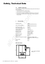
The PS 113 A is connected to the vacuum system via a DN 16 KF small flange. 

The PS 113 A should preferably be mounted standing on its flange. Inclined 
mounting is also permissible, including the horizontal position. Downward installa-
tion is not permissible because in such a case condensate may collect in the pres-
sure switch. This affects the measurements and may damage the pressure switch. 


3.2 Electrical 

Connection 


Fig. 2  Contact assignment of microswitch 
 

The contact assignment is given in Fig. 2. 

The PS 113 A is supplied with a connected 3 m long standard cable. The length of 
this cable may be changed. 

The electrical connection terminals and the strain relief are accessible after un-
screwing the cross head screws and folding out the cap. 

The contacts at the PS 113 A are marked 1, 2 and 3 (see contact assignment 
Fig. 2). 

The supply line has to be fuse-protected with max. 100 mA by the end-user. 

Adhere to the applicable regulations and take the necessary precautions for all 
work you are going to do. 


3.3 Start 

up 

When leak detecting with a helium leak detector, spraying the pressure switch with 
helium may result in a helium proof. This is in general not due to a leak of the 
PS 113 A, but is permeation of helium through the EPDM diaphragm. 


All manuals and user guides at all-guides.com

Содержание PS 113 A

Страница 1: ...PS Low Operat Part Num 230 011 S 11 w Pres ing Man ber 13 A ssure ual GA0 A Safet 09616_00 ty Sw 02_C0 witch All manuals and user guides at all guides com a l l g u i d e s c o m...

Страница 2: ...m systems It is used e g to automatically interrupt the gas supply when venting vacuum systems with a purge gas at a pressure of 3 mbar below atmos pheric pressure Unpacking and Checking Unpack the lo...

Страница 3: ...ric pressure an elastic diaphragm actuates a changeover contact which in turn may be used to directly switch any ancillary equipment The electrical connections are placed under a plastic cover Scope o...

Страница 4: ...ns 5 1 3 General Safety Instructions 5 1 4 Liability and Warranty 6 2 Technical Data 6 3 Installation 7 3 1 Vacuum Connection 7 3 2 Electrical Connection 7 3 3 Start up 7 4 Maintenance 8 5 Returning t...

Страница 5: ...y experience or who have been instructed by the end user of the product 1 3 General Safety Instructions Adhere to the applicable regulations and take the necessary precautions for the process media us...

Страница 6: ...6 mbar below atmospheric pressure Return switching pressure 3 mbar below atmospheric pressure Switching inaccuracy 2 mbar Max operating pressure abs 2000 mbar Operating temperature 0 to 85 C Helium p...

Страница 7: ...PS 113 A is supplied with a connected 3 m long standard cable The length of this cable may be changed The electrical connection terminals and the strain relief are accessible after un screwing the cr...

Страница 8: ...substances e g radioactive toxic caustic or microbiological Adhere to the forwarding regulations of all involved countries and forwarding companies and enclose a completed declaration of con taminati...

Страница 9: ...of in accordance with special regulations Dispose of such products in accordance with the relevant local regu lations Separating the components After disassembling the product separate its components...

Страница 10: ...Declaration of Contamination 10 GA09616_002_C0 2016 10 Leybold Declaration of Contamination All manuals and user guides at all guides com...

Страница 11: ...EU Declaration of Conformity GA09616_002_C0 2016 10 Leybold 11 EU Declaration of Conformity All manuals and user guides at all guides com a l l g u i d e s c o m...

Страница 12: ...0 Les Ulis cedex Sales and Service T 33 1 69 82 48 00 F 33 1 69 07 57 38 info ctb leybold com sales ctb leybold com Leybold France S A S Valence Factory 640 Rue A Berg s B P 107 F 26501 Bourg l s Vale...

Отзывы: