


17
DRYVAC
2
25/50/100 B Manual
GA 01.415/2.02 - 7/97
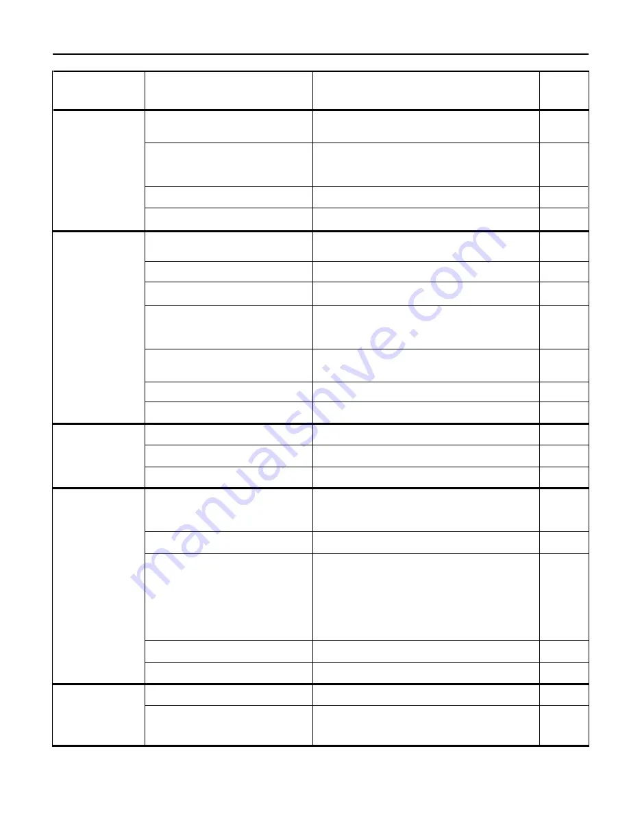
Pump rotation direction in incorrect;
see malfunction 1.2.
Too little lubricant in the gearbox.
Oil pump malfunction.
Switch, plug, or cord malfunction.
Intake pressure is too high in
continuous operation.
Exhaust pressure is too high.
Ambient temperature is too high.
Cooling air is restricted.
Incorrect AC power connection.
Pump contaminated by deposits.
Switch, plug, or cord malfunction.
Intake line is too long or too narrow.
Dirt trap at intake port is clogged.
Intake line is leaking or dirty.
Unsuitable measurement procedure
or measuring instrument.
Pump has external leak.
Evaporating liquids in pump.
Vacuum vessel is leaking or dirty.
Intake line is leaking or dirty.
Motor bearing failure.
Liquid “knocking" in pump. (Too
much liquid in pump.)
3. Oil pressure is
too low. Switch
has opened.
4. Motor tempera-
ture is too high.
Switch has
opened.
5. Evacuation
period is too
long. (Pumping
speed is to low.)
6. Pump does not
reach ultimate
pressure.
7. Pump is ex-
tremely loud.
Refer-
ences*
Symptom
Possible cause
Recommended corrective action
Disconnect the pump from the power supply.
Interchange two phases at your AC power source.
Measure the lubricant level via the fill plug. The target
value is 6 to 9 mm (
1
/
4
to
3
/
8
inch) for the 100B and
12 to 15 mm (
1
/
2
to
5
/
8
inch) for the 25/50B.
Repair the oil pump.
Replace malfunctioning part.
Modify the system.
Clean or modify the exhaust line.
Change site or supply cooler air.
Clean the ventilation grids and cooling air chan-
nels. Increase the distance between the vent grids
and the walls.
Change the connections in the motor junction box
to match the AC power source.
Rebuild the pump.
Replace malfunctioning part.
Install a shorter or wider diameter intake line.
Clean dirt trap.
Seal or clean the intake line.
Use correct measurement procedure with proper
measuring instrument. Check pressure directly at
pump intake port.
Find leak and repair pump.
Measure the partial pressure of non-condensable
gases. To do so, insert a cryo trap between the
gauge and the intake port. If the ultimate pressure
is reached using this measurement, there are
liquids evaporating in the pump. A possible remedy
is to allow the pump to run for half an hour without
process load.
Seal or clean vacuum vessel.
Seal or clean the intake line.
Replace or repair the motor.
Install the exhaust line with a downward slope
away from the pump, or install a condensate trap.
Section 5 — Troubleshooting
* This column refers to the section in the Operating instructions that contains the applicable repair information.
2.4
Service
Service
Service
1.4
2.6
---
---
2.2.2
Service
Service
2.5
---
---
---
Service
---
---
---
Service
2.6


