background image

Diagnostic Information

 16

4012-0XX

Print Quality Service Check

FRU Action

1

Print Cartridge

Be sure the machine has a known good 
print cartridge.

2

Printhead Carrier Assembly

Reseat the printhead cables in the printer 
board and check the following parts for 
wear or damage:

• Print Cartridge Latch 
• Latch Spring 
• Carrier 

3

Printer Board

Printhead Cable

Rubber Backer

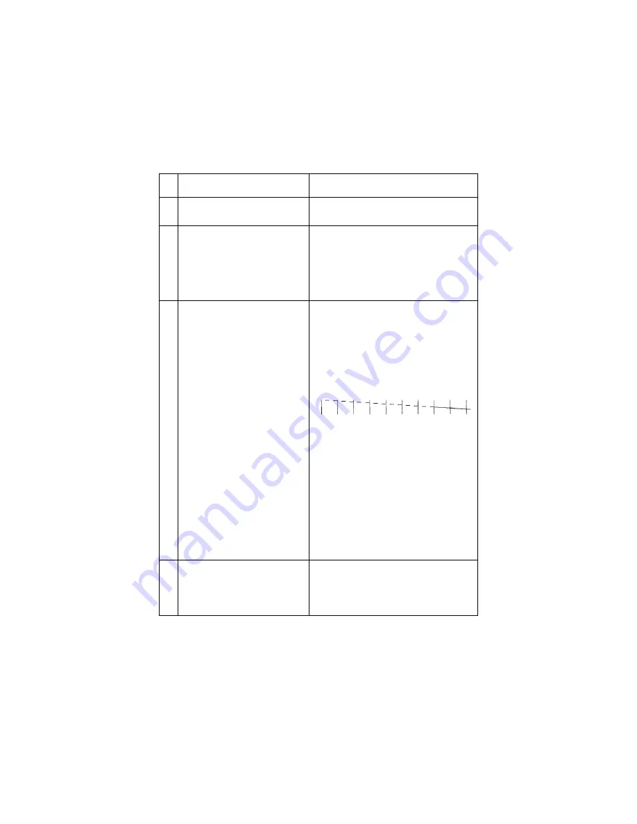
Perform the 

“Purge Test” on page 25

. Look 

for a break in the diagonal line at the bot-
tom of the test pattern. A broken line indi-
cates one or more print nozzles are 
clogged. Run the test again to verify the 
failure. If there are even breaks in the diag-
onal line similar to the pattern shown 
below, replace the printer board.
 

If there is a single break or random breaks 
in the diagonal line check the following: 

Check the gold-plated contacts on the end 
of the cable that connects to the carrier for 
dirt and wear. Use only a clean dry cloth to 
clean the contacts. Also check the cable 
for damage. You may need to remove the 
cable from the carrier to inspect it.
A worn rubber backer will result in poor 
contact between the printhead cable and 
the print cartridge. Check the rubber 
backer for wear. 

4

Maintenance Station

Intermittent nozzle failures can be caused 
by worn parts in the maintenance station. 
Go to and perform the 

“Maintenance Sta-

tion Service Check” on page 9

, then return 

to this check.

Содержание Medley 4012-005

Страница 1: ... MedleyTM Lexmark and Medley are trademarks of Lexmark International Inc registered in the United States and or other countries Table of Contents Index Safety and Notices Trademarks Start Diagnostics Main Menu ...

Страница 2: ...ay be made at any time Publications are not stocked at the address given below requests for pub lications should be made to your point of purchase Comments may be addressed to Lexmark International Inc Department D22A 035 3 740 New Circle Road Lexington Kentucky 40550 U S A Lex mark may use or distribute any of the information you supply in any way it believes appropriate without incurring any obl...

Страница 3: ...ervice Check 11 Printer Paper Feed Service Check 12 Printer Paper Path Service Check 15 Print Quality Service Check 16 Printing Problem Service Check 18 Scanner Document Feed Service Check 19 Scanner Service Check 20 Transport Service Check 21 Diagnostic Aids 22 Call Monitoring 22 Error Report 22 Frame Service Position 22 Hex Print Mode 22 Machine Checkout 23 Memory Test 23 Operator Panel Service ...

Страница 4: ...Cover 34 Right Side Cover 34 Left Side Cover 34 Operator Panel and Cover 34 Encoder Strip Removal 35 End of Forms Flag Removal 35 Exit Roller Assembly Removal 35 EPROM Removal 36 Fax Board Printer Board and LCU Board Removal 37 Feed Arm Assembly Removal 37 Inside Idler Gears Removal 37 Large Feed Roller Assembly Removal 38 Left Side Frame Removal 38 Maintenance Drive and Rocker Assemblies Removal ...

Страница 5: ...ntenance 54 Lubrication Specifications 54 Scanner Cleaning Procedure 55 Parts Catalog 56 How To Use This Parts Catalog 56 Assembly 1 Covers 57 Assembly 2 Frame 59 Assembly 3 Operator Panel 61 Assembly 4 Printer Paper Feed Assembly 63 Assembly 4 Printer Paper Feed Assembly cont 65 Assembly 5 Carrier 67 Assembly 6 Carrier Transport 69 Assembly 7 Maintenance Station 71 Assembly 8 Scanner 73 Assembly ...

Страница 6: ...e checks used to isolate failing field replaceable units FRUs 3 Diagnostic Aids contains tests and checks used to locate or repeat symptoms of printer problems 4 Repair Information provides instructions for making printer adjustments and removing and installing FRUs 5 Parts and Test Point Locations uses illustrations to identify the major components and test points on the printer 6 Preventive Main...

Страница 7: ...deren benuetzt werden Zusaetzliches Risiko eines elektrischen Schlags und koerperlicher Verletzung existiert waehrend des Auseinandernehmens und der Wartung des Geraets Fachpersonal sollte im vollen Verstaendnis der Lage entsprechende VorsichtsmaBnahmen ergreifen Ersatzteile muessen gleiche oder gleichwertige Merkmale wie die Originalteile aufweisen da Sicherheitsvorkehrungen nicht immer offensich...

Страница 8: ...no para cualquier otro usuario Existen mayores riesgos de descargas electricas y danos personales durante el desmontaje y la reparacion de la maquina El personal cualificado comprende esto y toma las precauciones necesarias Los dispositivos de seguridad de algunas partes quiza no siempre puedan ser reconocidas a simple vista Por lo tanto las partes de reemplazo deben poseer caracteristicas identic...

Страница 9: ...ix 4012 0XX Chinese Safety Information Korean Safety Information ...

Страница 10: ...edley uses a 300 x 300 dpi scanner for fast high quality scanning personal copying and faxing Scanning software for the PC is included with the Medley There are three models Medley 4c 4012 005 which does not include a handset Medley 4x 4012 006 which does include a handset and the Medley 4sx 4012 009 which is the same as the 4x but is shipped standard with the battery backup Other than in the Part...

Страница 11: ...ndard on Medley 4sx Maintenance Approach The diagnostic information in this manual leads you to the correct field replaceable unit FRU or part Use the error code charts symptom table service checks and diagnostic aids to determine the symptom and repair the failure Medley can be serviced without being connected to a host computer After you complete the repair perform tests as needed to verify the ...

Страница 12: ... Crystal Display LCU Line Connect Unit LED Light Emitting Diode NVRAM Nonvolatile Random Access Memory OEM Original Equipment Manufacturer PCA Printed Circuit Assemblies PICS Problem Isolation Charts PIXEL Picture Element POST Power On Self Test PQET Print Quality Enhancement Technology SRAM Static Random Access Memory UPR Used Parts Replacement V ac Volts alternating current V dc Volts direct cur...

Страница 13: ...Diagnostic Information 4 4012 0XX Diagnostic Information 9 Use the symptom table and service checks in this chapter to deter mine the failing part in a malfunctioning machine ...

Страница 14: ...k on page 21 Printer Code 3 8 Go to Transport Service Check on page 21 Printer Code 9 2 Replace the printer board EPROM if necessary replace the printer board Printer Code 9 4 Go to Transport Service Check on page 21 Power Problem No LEDs or LCD pixels light up during POR no machine activ ity Go to Power Service Check on page 11 Maintenance Station Problem Maintenance station does not move or fail...

Страница 15: ...jam problem Go to Scanner Document Feed Service Check on page 19 Printing Problem Test prints faxes or printer jobs do not print correctly not a print quality problem Go to Printing Problem Service Check on page 18 Print Quality Problem Test prints faxes and printer jobs print but output has voids or uneven density or is fuzzy smudged or faint Go to Print Quality Service Check on page 16 Scanning ...

Страница 16: ... tone and a 1650Hz 1850Hz warbling handshaking tone from the called machine Check the connections of LCU card J2 to fax card J11 If the problem still exists replace the LCU board and then if neces sary the fax board 2 Cannot receive faxes Machine not set for auto answer TEL and LINE connections reversed A telephone on the same line is already off hook Machine connected to the wrong tele phone line...

Страница 17: ... Flag Check the flag for binds or damage 2 Printer End of Forms Sensor Check the sensor for dirt 3 Printer Board Check the End of Forms sensor measure the voltage at pin 2 of U28 on the printer board The voltage should change from 0 to 5 V dc as you block and unblock the End of Forms sensor S1 4 Feed Arm Assembly Check all parts of the feed arm assembly for binds wear or damage 5 Software Setting ...

Страница 18: ...replace the maintenance drive assembly Check for motor pins shorted to the motor housing If you find a shorted pin replace the maintenance drive assembly If the symptom remains replace the printer board A bind in the drive assembly can prevent the motor from turning Check for binds and loose or worn parts in the drive assembly Also check the motor gear 2 Printer Board Turn the machine off and disc...

Страница 19: ...hine before you reconnect the power supply to the fax board 2 Operator Panel Board Operator Panel Cable Perform the Operator Panel Test see Operator Panel Test on page 24 If some of the buttons do not work check the contacts on the back of the keypads and the surface of the lands on the opera tor panel board Replace the keypads as necessary Check the continuity of the operator panel cable before r...

Страница 20: ...e replace the power supply Be sure to unplug the machine before you reconnect the power supply to the boards 2 Printhead Cable Parallel Cable Unplug the machine Disconnect one of the listed components and plug in the machine Look for a symptom change Check the failing part for shorts and replace as necessary Repeat this proce dure for the remaining listed parts 3 Printer Board Disconnect the fax b...

Страница 21: ...t Feed 150 sheets or less depending on the thickness Make sure the correct type of paper is in the machine Check for static in the paper Make sure the rear of the carrier guide is on top of the paper guide FRU Action 1 Printer Board With J5 disconnected and power on check for 24 V dc between J5 3 and ground and between J5 4 and ground on the printer board If the voltage is not present check for mo...

Страница 22: ... shorted to the motor housing If you find a shorted pin replace the motor If the failure remains replace the printer board Although the paper feeds in a forward direction only the paper feed motor turns in two directions If the paper feed motor turns in one direction only replace the printer board Binds in the paper feed motor or gear train can cause intermittent false paper jam errors Remove the ...

Страница 23: ... Rollers Envelope Bucklers All parts inside the left and right edge guides 6 End of Forms Flag Check for binds or damage 7 Star Rollers Check for worn or binding rollers Check for broken star roller springs 8 Ejectors After the paper exits from the exit rollers the paper feed motor reverses causing the feed arm pawl to restore to the home posi tion in the ASF side plate At the same time the paper ...

Страница 24: ... by one tooth in the ASF frame Check the following for wear or damage Envelope Bucklers All parts inside the left and right edge guides 4 End of Forms Flag Check for binds or damage 5 Exit Roller Check for wear or binds 6 Star Rollers Check for wear or binds Check for broken star roller springs 7 Ejectors Check the front cover if it is installed incorrectly it can interfere with the ejectors Make ...

Страница 25: ... If there are even breaks in the diag onal line similar to the pattern shown below replace the printer board If there is a single break or random breaks in the diagonal line check the following Check the gold plated contacts on the end of the cable that connects to the carrier for dirt and wear Use only a clean dry cloth to clean the contacts Also check the cable for damage You may need to remove ...

Страница 26: ... paper by moving slightly faster than the feed rollers A binding star roller can put vertical marks on the paper Subframe is properly snapped into posi tion 6 Transport Blurred print and voids can be caused by problems in the transport area Check the following Transport belt for wear Carrier guide and carrier guide rod for wear or dirt Idler pulley parts for wear damage or looseness Encoder strip ...

Страница 27: ...gether and try to run the test again If the test still does not start go to Power Service Check on page 11 2 The machine responds but does not complete the test Refer to the appropriate service check for the symptom 3 The tests prints correctly There is a problem with the print job the parallel cable the LCU board the fax board the fax LCU cables or the printer fax cable Check the cables and their...

Страница 28: ...are undam aged Refer to Scanner Cleaning Proce dure on page 55 2 Paper Sensors The operator panel message should change when a document is fed into the scanner Check for fax board J6 3 to change from 0 V dc to 5 V dc as the entry sensor flag is toggled Check for fax board J6 6 to change from 0 V dc to 5 V dc as the second sensor flag is toggled 3 Motor Fax board J3 5 and J3 6 should have 15 V dc W...

Страница 29: ...ge a black image or an image with one or more thin vertical black lines Replace the scanner CCD unit It is not possible to be certain whether an all black or all white scan failure is due to the CCD unit or the fax board In general if the machine performs non scanning functions involving the fax board for example receiving a fax exchanging stored data with the PC or accepting data entered from the...

Страница 30: ...e the printer board 2 Printer Board Unplug the machine and disconnect J6 from the printer board Plug the machine in and check for a pulse of 3 to 5 V dc between J6 1 and ground and between J6 2 and ground on the printer board as the machine goes through POST 3 Transport Belt Carrier Guide or Guide Rod Idler Pulley Parts Cable Clip Check for worn loose or broken parts Clean the carrier guide rod Do...

Страница 31: ...boards the frame can be piv oted out of the way without being removed Remove the covers Dis connect the cables from the frame on the right side of the printer and fax boards Unsnap the right front and right rear frame supports from the machine base Pivot the printer frame up 90 on the left feet Hex Print Mode Perform this test with a black print cartridge installed Use hex mode to help evaluate da...

Страница 32: ...K Receiving a fax to memory confirms that the telephone connection and the memory on the fax board are good Memory Test Use the Memory Test for testing both system memory and document memory 1 Press Setup 2 Press 2104 to enter the Service Functions menu 3 Press the right arrow key to select Testing then press OK 4 Select MEM 5 Press Stop several times to exit the test Operator Panel Service Positi...

Страница 33: ... be pressed with a small tool or straightened paper clip The Reset button does a hardware reset of the fax board and opera tor panel Pressing Reset does not erase stored faxes or the con tents of the phone book The Reset button does not reset the printer board unplugging the machine resets the printer board Print Engine Test Use the Print Engine test for testing the printer board and inkjet printe...

Страница 34: ...t with either the black or the color cartridge installed 1 Press Setup 2 Select PRT 3 Select PUR 4 Press Stop several times to exit the menus Scanner Feed Test This test exercises the scanner Automatic Document Feed to allow you to verify the paper pick and scanner motor function This test feeds paper but does not test scanning 1 Press Setup 2 Press 2104 to activate the Service Functions menu 3 Us...

Страница 35: ... Stop several times to exit the service menus Test Print From the operator panel print the Setup Conditions report press Setup then press the button for LST to determine that the operator panel the fax board the printer board the ASF and the print engine are performing correctly There are two other test prints available Press Setup then the but ton for PRT Press the right arrow to select Diag and ...

Страница 36: ...ad page 28 before handling elec tronic parts Warning Medley has a soft power key which does not remove machine power it shuts down visible machine activity When the machine is plugged in power is always present on the fax board and printer board Before connecting or disconnecting any machine com ponents always unplug the machine from the wall outlet ...

Страница 37: ... the ESD sensitive part by its edge connector shroud cover do not touch its pins If you are removing a pluggable module use the correct tool Do not place the ESD sensitive part on the machine cover or on a metal table if you need to put down the ESD sensitive part for any reason first put it into its special bag Machine covers and metal tables are electrical grounds They increase the risk of damag...

Страница 38: ...pattern prints The pattern con sists of three lines of vertical bars The bars are aligned when the adjustment is correct The following sample requires the cen ter vertical bars to be moved to the right 4 The center bars can be aligned in increments of 1 1200 0 02 mm If the lines are not straight press the left arrow key to move the center of the lines to the left or press the right arrow key to mo...

Страница 39: ...wer from the electronics Auto Sheet Feed ASF Assembly Removal 1 Remove the paper load lever 2 Remove the left and right side covers 3 Remove the clip from the right side subframe if installed 4 Remove the top cover 5 Release the latches holding the subframe to the ASF 6 Push in the two latches A that secure the ASF to the side frame then lift up the sheet feed to remove it from the machine When yo...

Страница 40: ...u reinstall this shaft it must be parallel with the ASF housing 6 Pivot the guide assembly up and pry it off the back plate Battery Option 1 Unplug the machine 2 Open the access door on the left side cover The battery option is attached to the door 3 Disconnect the battery option cable from the fax board 4 Remove the battery board mounting screw Note If the battery option is being replaced install...

Страница 41: ... above the frame Remove the carrier guide rod to the right above the carrier motor Be careful not to damage the encoder strip 9 Pull the ends of the printhead cables into the machine then remove the cables from the four retainers in the paper guide starting from the right Carrier Transport Belt Removal 1 Open the top cover and then remove the left and right side covers 2 Move the carrier in line w...

Страница 42: ...emove the scanner and subframe 6 Move the carrier in line with the opening in the carrier transport motor frame 7 Reach through the opening and pull the belt from the carrier 8 To unlock the carrier guide rod latches rotate the rod top to rear Gently push the carrier guide rod latches at each end of the rod to the rear and lift up the rod until the sensor on the carrier clears the encoder strip Re...

Страница 43: ...1 Remove the paper load lever 2 Open the operator panel cover and the top cover 3 Remove the screw from inside the subframe just above scanner 4 Lift on the top inner edge of the cover to free the top latches 5 Rotate the cover to the right to free the lower latches Left Side Cover 1 Open the operator panel cover and the top cover 2 Remove the screw from inside the subframe just above scanner 3 Li...

Страница 44: ...e left 6 Remove the encoder strip from the right latch When you install the encoder strip be sure it is fully seated on the left mounting peg End of Forms Flag Removal 1 Remove the covers 2 Disconnect the printer board connectors J1 J2 J4 J5 and J6 3 Disconnect the fax board connectors J3 and J8 4 Raise the machine frame into the service position 5 Pivot the weighted end of the end of forms flag t...

Страница 45: ...J3 from the fax board 6 Release the latches at the right front and right rear legs of the frame then lift and pivot the frame 90 to the left into the service position 7 Gently pry the EPROM from the board 8 To install the EPROM a Ensure the orientation notch is to the right for the fax board or to the front for the printer board Refer to Parts and Test Point Locations on page 49 b Ensure that each...

Страница 46: ...le tie around the support posts 8 Remove the EPROM see EPROM Removal on page 36 for installation on the new board Remove the ground screw and remove the board Note If the printer board is replaced check the bidirectional align ment If the fax board is replaced inspect the LCU board for physical damage Replace the LCU board if damage is present The machine serial number needs to be saved into memor...

Страница 47: ...elease the latches at the right front and right rear legs of the frame then lift and pivot the frame 90 to the left Lift the frame to disengage the left legs from the base 8 Move the carrier in line with the opening in the carrier transport motor frame 9 Reach through the opening and pull the belt from the carrier 10 To unlock the carrier guide rod latches rotate the rod top to rear Gently push th...

Страница 48: ...me align the right side frame latch with the latching surface on the middle frame before you align the roller shafts and carrier guide It may be easier to do this with the machine on its right side Maintenance Drive and Rocker Assemblies Removal 1 Remove the covers 2 Remove the ASF 3 Remove the right side frame 4 Gently unlatch the maintenance assembly latches 5 Slide out the maintenance drive ass...

Страница 49: ... Remove the small feed roller shaft 12 Remove the large feed roller shaft and springs 13 Remove the end of forms flag 14 Remove the right side frame 15 Remove the maintenance station Outside Idler Gears Removal 1 Remove the right cover 2 Disconnect the printhead cables from the printer board 3 Each gear is latched in place Push up the latch and remove the gear from the side frame stud by pulling t...

Страница 50: ... the left side frame to the left 7 Disengage the right side of the paper guide from the latch and lift it from the machine When you reinstall the paper guide be sure the front edge goes under the rear of the carrier guide If the paper guide is on top of the carrier guide push down the front bottom edge It will snap under the carrier guide Paper Release Lever Removal 1 Remove the left cover 2 Pull ...

Страница 51: ... tom shield Note Make sure the ground screw is secure when reinstalling the power supply 10 Unsnap the front latch and lift the power supply from the machine Make sure the power supply insulator remains in place when reinstalling the power supply Print Engine Removal 1 Unplug the machine before beginning any electrical service The power key does not remove power from the electronics 2 Remove the l...

Страница 52: ...he cable clip A from the left side of the carrier 6 Remove the pointer from the front of the carrier 7 Remove the two sensor mounting screws 8 Push down the two latches that secure the cradle to the carrier and pull the cradle up from the carrier 9 Remove the printhead cable from the alignment pins The new cable comes without the folds in it Place the new cable next to the old cable and fold the n...

Страница 53: ... Many of the parts are held in place with plastic latches To remove such parts press the hook end of the latch away from the part to which it is latched The latches break easily Release them carefully Never apply excessive force when releasing the hook Hook ...

Страница 54: ...ach through the opening and pull the belt from the carrier 10 To unlock the carrier guide rod latches rotate the rod top to rear Gently push the carrier rod guide latches at each end of the rod to the rear and lift up the rod until the sensor on the carrier clears the encoder strip Remove the carrier rod guide through the opening in the left side frame Be careful not to damage the encoder strip 11...

Страница 55: ...te For reassembly you may want to remove the carrier guide and reinstall it after you install the paper guide When you reinstall the paper guide be sure the front edge goes under the rear of the carrier guide If the paper guide is on top of the carrier guide push down the front bottom edge It will snap under the carrier guide To install the right side frame onto the middle frame align the right si...

Страница 56: ...e with the opening on the carrier transport motor frame 4 Reach through the opening and pull the belt from the carrier 5 To unlock the carrier guide rod latches rotate the rod top to rear Gently push the carrier guide rod latches at each end of the rod to the rear and lift up the rod until the sensor on the carrier clears the encoder strip Place the carrier on top of the paper guide 6 A latch on t...

Страница 57: ...of the scanner to the subframe 8 Lift the scanner from the machine 9 Disconnect the speaker from the fax board J5 10 Slide the speaker toward the front to remove it Subframe Removal 1 Remove the left and right side covers 2 Remove the rear cover 3 Remove the top cover the operator panel cover and the front cover 4 Disconnect the four scanner cables J3 J6 J7 J8 and the speaker cable J5 from the fax...

Страница 58: ...9 Parts and Test Point Locations 9 LCU Board LCU Board Connector Name J1 Handset J2 Phone Data to Fax Board J3 Parallel Port J4 Parallel Data to Fax Board TJ1 Phone Line In TJ2 External Phone TJ2 TJ1 J3 J1 J2 J4 ...

Страница 59: ...Parts and Test Point Locations 50 4012 0XX Fax Board J4 J5 J6 J7 J8 J9 J10 J11 J12 J1 J2 J3 ...

Страница 60: ...Board J2 Power Supply J3 Scanner Motor J4 Operator Panel J5 Speaker J6 Scanner Paper Sensors J7 LED Array Scanner Closed Switch J8 Scanner Data J9 Battery Backup Option J10 Memory Option J11 Phone Data from LCU Board J12 Parallel Data from LCU Board ...

Страница 61: ...Parts and Test Point Locations 52 4012 0XX Printer Board Printer Board Connector Name J1 Printhead J2 Printhead J3 Not Used J4 Maintenance Motor J5 Paper Feed Motor J4 J5 J6 J7 EPROM S1 J9 J11 J1 J2 ...

Страница 62: ...4012 0XX 53 J6 Carrier Motor J7 POR Test Jumper J8 Not Used J9 J9A Fax Board J10 Not Used J11 Power Supply Printer Board Connector Name ...

Страница 63: ...e Use only mineral oil based grease Use a mineral oil based grease to lubricate the following All gear mounting studs Right end of the exit roller at the right side frame Right end of the small feed roller at the right side frame Left end of the large feed roller at the left side frame Both ends of the ASF pick roll shaft at the ASF side frames Transport belt idler pulley hole Inside surface of th...

Страница 64: ...ff the scanner white reference strip inside the front frame with a clean cloth If neces sary use isopropyl alcohol The scanner lenses and mirrors do not normally require clean ing the microcode compensates for dust on the optical surfaces If however these surfaces become unusually dirty or the scanned image becomes fuzzy remove the scanner and clean the mirrors and lenses with isopropyl alcohol Ca...

Страница 65: ...ommon parts are shown by one index number Parts peculiar to one or the other of the assemblies are listed separately and identified by description AR As Required in the Units column indicates that the quantity is not the same for all machines NS Not Shown in the Asm Index column indicates that the part is procurable but is not pictured in the illustration PP Parts Packet ...

Страница 66: ...4012 0XX 57 Assembly 1 Covers 9 19 1 20 21 3 6 4 10 5 15 8 2 11 22 7 ...

Страница 67: ...9 6 Paper Load Lever 69G6888 69G6888 7 Left Side Cover 69G6870 69G6893 NS Screw Left Side Cover PP 69G6846 8 Bezel front 69G6861 69G6861 9 Handset w Cable N A 69G6822 10 Cradle Handset N A 69G6894 NS Screw Cradle Mounting PP 69G6846 11 Left output Guide 1367493 1367493 15 Extender Input Tray Printer 69G6890 69G6890 19 Panel Scan Input Tray 69G6889 69G6889 20 Tray Scan Input 69G6891 69G6891 21 Exte...

Страница 68: ...4012 0XX 59 Assembly 2 Frame 2 9 10 3 4 1 8 8 6 5 7 ...

Страница 69: ...ide Frame 1367209 1367209 3 MIddle Frame Asm 1367219 1367219 4 Right Side Frame 1367229 1367229 5 Carrier Transport Motor Frame 1367309 1367309 6 Exit Tray Asm 69G6824 69G6824 7 Carrier Guide 1367079 1367079 8 Foot 69G6860 69G6860 9 Leg left Rear 69G6882 69G6882 10 Leg left Front 69G6883 69G6883 ...

Страница 70: ...4012 0XX 61 Assembly 3 Operator Panel 9 3 10 2 1 6 5 4 8 7 11 ...

Страница 71: ...rlay Sm Operator Panel 69G6897 69G6898 NS Shield Reset Button PP 69G6846 4 Keypad Left 69G6896 69G6896 5 Keypad Center 69G6895 69G6895 6 Keypad Right 69G6884 69G6884 7 Operator Panel Board 69G6806 69G6806 8 Lens Display 69G6831 69G6831 9 Door Button 69G6887 69G6887 10 Shield Directory PP 69G6846 NS Cable Operator Panel Cable to Fax Board 69G6878 69G6878 11 Shield EMC 69G6903 69G6903 ...

Страница 72: ...4012 0XX 63 Assembly 4 Printer Paper Feed Assembly 4 6 7 9 8 1 2 3 5 ...

Страница 73: ...se Lever 1367179 1367179 2 Bushing PP 1367169 3 Paper Guide 1367339 1367339 4 Small Feed Roller Asm 1367279 1367279 5 Exit Roller Asm 1367289 1367289 6 Ejector B M 1367266 1367266 7 Spring PP 1367169 8 End of Form Flag 1367049 1367049 9 Large Feed Roller Asm 1367269 1367269 ...

Страница 74: ...4012 0XX 65 Assembly 4 Printer Paper Feed Assembly cont 11 13 12 11 10 14 ...

Страница 75: ...tion 4012 005 P N 4012 006 4012 009 P N 10 Paper Feed Motor 1367239 1367239 NS Toroid Paper Feed Motor 1374338 1374338 11 Gears B M 1367249 1367249 12 Feed Arm Asm 1367259 1367259 13 C Clip PP 1367169 14 Screw PP 1367169 ...

Страница 76: ...4012 0XX 67 Assembly 5 Carrier 3 1 4 6 1 2 5 ...

Страница 77: ... N 4012 006 4012 009 P N 1 Carrier Asm 1367299 1367299 2 Printhead Cable 1367149 1367149 NS Toroid Printhead Cable 1374338 1374338 3 Screw PP 1367169 4 Rubber Backer 1367109 1367109 5 Carrier Guide Rod 1367089 1367089 6 Clip PP 1367169 ...

Страница 78: ...4012 0XX 69 Assembly 6 Carrier Transport 1 2 4 5 3 6 7 ...

Страница 79: ...05 P N 4012 006 4012 009 P N 1 Carrier Motor 1367319 1367319 2 Screw PP 1367169 3 Carrier Belt 1367359 1367359 4 Encoder Strip 1367379 1367379 5 Star Roller Asm 1425705 1425705 6 Spring PP 1367169 7 Idler Pulley B M 1367329 1367329 ...

Страница 80: ...4012 0XX 71 Assembly 7 Maintenance Station 3 1 4 2 ...

Страница 81: ... 4012 0XX Description 4012 005 P N 4012 006 4012 009 P N 1 Maintenance Station Rocker Asm 1425669 1425669 2 Maintenance Station Drive Asm 1367399 1367399 3 Wiper Cap B M 1367389 1367389 4 Screw PP 1367169 ...

Страница 82: ...4012 0XX 73 Assembly 8 Scanner 3 6 9 10 7 1 4 2 8 5 14 12 13 ...

Страница 83: ...ar Kit 3 Gears 69G6844 69G6844 6 Pad Unit 69G6845 69G6845 7 LED Frame Switch Asm 69G6841 69G6841 8 Motor Assembly 69G6842 69G6842 9 L P Sensor 69G6839 69G6839 NS Screws PP 69G6846 10 Paper Path Cover 69G6855 69G6855 12 Subframe Scanner 69G6833 69G6833 13 Cap Bracket Asm 69G6835 69G6835 14 Speaker 69G6838 69G6838 NS Jumper Front Frame ESD Gnd 69G6862 69G6862 NS Shield Scanner 69G6863 69G6863 ...

Страница 84: ...4012 0XX 75 Assembly 9 Electronics ...

Страница 85: ...rinter Card 1375418 1375418 8 LCU Card w Bezel 69G6808 69G6801 9 Shield LCU Card 69G6880 69G6880 10 Shield Printer 69G6881 69G6881 11 Shield Asm Bottom 69G6837 69G6837 14 Line Cord U S 69G6868 69G6868 15 Cable Telephone 69G6892 69G6892 NS Toroid Printer Fax Cable 69G6906 69G6906 16 Cable Printer to Fax 69G6872 69G6872 17 Cable Scanner to Fax 69G6873 69G6873 18 Cable Fax to LCU Digital 69G6876 69G6...

Страница 86: ...4012 0XX 77 Assembly 10 Automatic Sheet Feed ASF 10 4 2 7 6 11 1 8 7 9 3 5 ...

Страница 87: ...425578 1425578 3 Pick Roll Paper Load B M 1367469 1367469 4 Pick Roll Hub Asm 1367463 1367463 5 Paper Load Arm 1425580 1425580 6 Envelope Buckler B M 1367019 1367019 7 Side Back Plate B M 1425582 1425582 8 Gears B M 1367249 1367249 9 E Ring PP 1367169 10 Screw PP 1367169 11 Manual Insert Tray Printer 1425585 1425585 ...

Страница 88: ...4012 005 P N 4012 006 4012 009 P N 1 Memory Option 1MB 2 modules 69G6803 69G6803 2 Memory Option 3MB 6 modules 69G6804 69G6804 3 Battery Option 69G6807 69G6807 NS Screw Battery Mounting PP 69G6846 4 Demo code ROM 4012 011 4012 012 69G6811 69G6811 ...

Страница 89: ...Aids 22 Diagnostic Information 4 E Encoder Strip Removal 35 End of Forms Flag Removal 35 Envelope Feed Service Check 8 EPROM Removal 36 Error Report 22 Exit Roller Assembly Removal 35 F Fax Board Printer Board and LCU Board 37 Feed Arm Assembly Removal 37 First Print Line Service Check 8 Frame Service Position 22 G General Information 1 H Handling ESD Sensitive Parts 28 Hex Print Mode 22 How To Us...

Страница 90: ...al 42 Print Engine Test 24 Print Quality Service Check 16 Printer Paper Feed Service Check 12 Printer Paper Path Service Check 15 Printhead Cable Removal 43 Printing Problem Service Check 18 Purge Test 25 R Releasing Plastic Latches 44 Removal Procedures 30 Repair Information 27 Reset Button 24 Right Side Frame Removal 45 Rubber Backer Removal 47 S Safety Information vii Scanner And Speaker Remova...

Отзывы: