background image

Repair information

4-47


4513-630, -63W, -6EW

Re-installation note: 

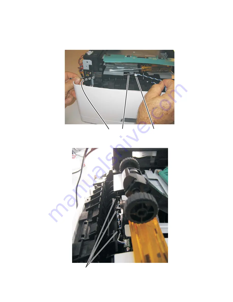
Prop open the duplex door, and insert the hook end of the spring hook through the frame opening (C) from 
the controller board side. Extend the hook until the sensor connector can be hooked.

Hook the spring hook (D) to the connector (E), and pull it through the opening.

Place the sensor into position, and reconnect the cable on the controller board.

Using the spring hook, be sure to reroute the cable through the three retainers (F) between the sensor and 
side frame.

Note:  

If the cable is not properly installed in its retainers, then the loose cable will obstruct the paper path.

E

D

C

F

Содержание 4513-630

Страница 1: ...4513 6EW Table of contents Start diagnostics Safety and notices Trademarks Index Lexmark and Lexmark with diamond design are trademarks of Lexmark International Inc registered in the United States an...

Страница 2: ...ppropriate without incurring any obligation to you References in this publication to products programs or services do not imply that the manufacturer intends to make these available in all countries i...

Страница 3: ...1 User status and attendance messages 2 1 Overview of the operator panel and menus 2 2 Diagram of the printer menus 2 4 Messages and error codes 2 5 User attendance messages 2 5 Cartridge error messa...

Страница 4: ...ck 2 42 2 42 Diagnostic aids 3 1 Accessing service menus 3 1 Configuration menu CONFIG MENU 3 2 Entering Configuration Menu 3 2 Available menus 3 2 Maintenance Count Value Maint Cnt Value 3 3 Reset Ma...

Страница 5: ...Dark Adj 3 16 Reports 3 16 Event log 3 16 Display Log 3 16 Print Log 3 17 Clear Log 3 17 Exit Diagnostics 3 17 Printhead assembly electronic adjustment 3 18 Printhead assembly mechanical adjustment 3...

Страница 6: ...roll removal 4 67 Upper front guide assembly removal 4 68 Wear strip tray 1 and 250 sheet tray 2 removal 4 69 Wear strip 550 sheet tray 2 removal 4 70 Locations and connections 5 1 Locations 5 1 Front...

Страница 7: ...er oder bei ordnungsgem er Wartung durch den Kundendienst Laserbestrahlung die Klasse I bersteigen w rde Menschen keinesfalls erreicht Avis relatif l utilisation de laser Pour les Etats Unis cette imp...

Страница 8: ...de pot ssio de 7 milliwatts operando numa faixa de comprimento de onda entre 655 e 675 nan metros O sistema e a impressora laser foram concebidos de forma a nunca existir qualquer possiblidade de ace...

Страница 9: ...itettaessa olet alttiina n kym tt m lle lasers teilylle l katso s teeseen VARNING Osynlig laserstr lning n r denna del r ppnad och sp rren r urkopplad Betrakta ej str len Laser notis Denna skrivare r...

Страница 10: ...IEC 60825 1 Els productes l ser de classe I no es consideren perillosos Aquesta impressora cont un l ser de classe IIIb 3b d arseni r de gal li nominalment de 7 mil liwats i funciona a la regi de long...

Страница 11: ...Notices and safety information xi 4513 630 63W 6EW...

Страница 12: ...xii Service Manual 4513 630 63W 6EW...

Страница 13: ...qualifi Le d montage et l entretien de ce produit pouvant pr senter certains risques lectriques le personnel d entretien qualifi devra prendre toutes les pr cautions n cessaires ATTENTION Ce symbole...

Страница 14: ...aci n sobre el mantenimiento de este producto est dirigida exclusivamente al personal cualificado de mantenimiento Existe mayor riesgo de descarga el ctrica y de da os personales durante el desmontaje...

Страница 15: ...t producte est orientada exclusivament a professionals i no est destinada a ning que no ho sigui El risc de xoc el ctric i de danys personals pot augmentar durant el proc s de desmuntatge i de servei...

Страница 16: ...ions to prevent problems 7 Parts catalog contains illustrations and part numbers for individual FRUs Change history Conventions Note A note provides additional information Warning A warning identifies...

Страница 17: ...Conventions xvii 4513 630 63W 6EW CAUTION This type of caution indicates a hot surface CAUTION This type of caution indicates a tipping hazard...

Страница 18: ...xviii Service Manual 4513 630 63W 6EW...

Страница 19: ...d and 360dn see the 4513 420 430 service manual minute on letter size media 29 ppm on A4 25ppm on legal Maintenance approach The diagnostic information in this manual leads to the correct field replac...

Страница 20: ...e control panel consists of these items A 4 line liquid crystal display APA that can show both graphics and text Eight buttons Back Menus Stop Select and Navigation up arrow down arrow left arrow and...

Страница 21: ...slots 1 1 Flash memory option card 2 2 Both slots are active for either a 256MB Flash memory card a font card or a DLE Multiple Flash font or DLE cards are not supported Item 4513 630 Lexmark E460dn...

Страница 22: ...patibility Windows Macintosh Linux Windows Macintosh Linux Standard local connections Parallel x USB Standard network connections Ethernet 10 100 Base Tx Wireless ethernet 802 11b g n x Optional local...

Страница 23: ...Manual integrated print duplex Integrated Integrated Envelope conditioning x x Available output trays Standard 150 sheet sensing bin Toner and photoconductor Toner cartridge 1 500 standard pages SWE...

Страница 24: ...transparency recycled labels bond letterhead preprinted colored paper light paper heavy paper rough cotton custom type x 60 163 g m 16 43 lb 50 paper 15 lables 10 transparencies Card stock 120 163 g m...

Страница 25: ...er end feed rolls C D 59 8 mm D Input sensor D E 44 9 mm E Transfer roll E F 112 7 mm F Fuser F G 21 4 mm G Fuser exit rolls G H 114 8 mm H Fuser exit sensor H I 7 5 mm I Exit rolls I J 17 0 mm J Exit...

Страница 26: ...icators on the 250 sheet tray before pushing the tray into the printer Make sure paper guides are positioned before loading the paper or specialty media Do not remove trays while a job is printing Bef...

Страница 27: ...eld Replaceable Unit HBP Host Based Printing HVPS High Voltage Power Supply LCD Liquid Crystal Diode LED Light Emitting Diode LSU Laser Scanning Unit LVPS Low Voltage Power Supply NVRAM Nonvolatile Ra...

Страница 28: ...1 10 Service Manual 4513 630 63W 6EW...

Страница 29: ...five digits are shown User status and attendance messages User status messages provide the user with information on the current status of the printer Ready displays on the first line of the display un...

Страница 30: ...us Press twice to exit the menus and return to the Ready state Press to stop printer activity Press to cancel a print job Stopping will display momentarily Stopped will then display to offer a list of...

Страница 31: ...f the light is solid green then the printer is on but idle If the light is blinking red then operator panel intervention is needed Display panel The display shows messages describing the current state...

Страница 32: ...Multipage Order Multipage View Multipage Border Job Menu Reset Printer Utilities Menu Print Menus Print Stats Print Net Setup Print Fonts Print Directory Factory Defaults Format Flash Defragment Flas...

Страница 33: ...e message to clear Disabling Menus Wait for the message to clear Note The printer settings cannot be changed from the control panel while the menus are disabled Enabling Menus Wait for the message to...

Страница 34: ...he Ready message Printing Directory List The printer is processing or printing a directory of all files stored in flash memory Wait for the message to clear Printing Font List The printer is processin...

Страница 35: ...y Full error Res Reduced remains on the display while the job prints Restoring Factory Defaults Wait for the message to clear Note When factory default settings are restored All downloaded resources f...

Страница 36: ...Cartridge has run past it s life such that the cartridge has to been totally void of printable toner During development it could also have the wrong chip installed 31 XX Defective cartridge errors 31...

Страница 37: ...ze sensing problem and media slippage First remove the PC kit and paper or debric at the input sensor Then inspect the flag on the input sensor It should rotate freely Replace the sensor if necessary...

Страница 38: ...removal on page 4 46 Verify that the media is approved Inspect the wear strips in the input tray and replace if necessary 200 16 Transport motor error detected Inspect the main motor See Main motor s...

Страница 39: ...guide assembly with sensor and reversing solenoid removal on page 4 60 200 32 Media more than 14 inches too long over the manual feeder sensor Possible causes include multi sheet feed or pre staged m...

Страница 40: ...an intended 201 27 Page at fuser nip before fuser reached acceptable operating temperature Page arrived at fuser earlier than expected so it was probably staged prematurely 202 00 Paper jam around exi...

Страница 41: ...ing from the duplex 233 03 Paper never reached the input sensor but was detected at the manual feed sensor 234 01 Duplex sensor covered during warm up 235 01 Invalid duplex media Check the media Duple...

Страница 42: ...strips and replace if necessary 251 00 Paper jam near the manual feeder Inspect the pick roller on the MPF or the rollers on the manual feed If the MPF pick roller is damaged or worn then replace the...

Страница 43: ...26 920 01 Fuser took too long to heat up after transitioning to new enhanced mode 920 02 Fuser fell too far below desired temperature while printing 920 03 Fuser too cool while checking for slope chan...

Страница 44: ...sers 924 02 Open thermistor check failure The ADC failed to converge Possible noisy thermistor signal This applies to the fuser and belt fusers 925 xx Wrong fuser installed The fuser type stored in th...

Страница 45: ...elim amp state 935 16 Printhead open loop error enable amp Kp state 935 17 Printhead closed loop error amp Kp failed to converge 935 18 Printhead closed loop error enable amp Ki state 935 19 Printhead...

Страница 46: ...etween EEPROM and mirror memory Note A new controller board or operator panel has been installed and has not been properly prepared for this use Install a new note Do not install both the controller b...

Страница 47: ...ring initialization Replace the controller board See Controller board service check on page 2 23 959 24 EEPROM retention error 959 25 Insufficient device space during HW prog 959 26 Incremental counte...

Страница 48: ...error detected by the specified device 983 xx Invalid command received by the specified device 984 xx Invalid command parameter received by the specidied device Call the next level of support 990 xx A...

Страница 49: ...See Cover interlock switch service check on page 2 24 POST completes but the LCD does not come on See Operator panel service check on page 2 28 Main motor does not come on See Main motor service chec...

Страница 50: ...ee Operator panel service check on page 2 28 Operator panel lights are off or very dim See Operator panel service check on page 2 28 Blank page See Blank page on page 2 31 Black page See Black page on...

Страница 51: ...not power up without a functioning operator panel 4 The controller board assembly The LED adjacent to J12 will be illuminated if the card is powered and good 5 The operator panel See Operator panel se...

Страница 52: ...oller board assembly should apply 24 V dc to pin 2 If voltage is not present then check or replace the controller board See Controller board removal on page 4 6 If voltage is present then check pin 1...

Страница 53: ...ty If open then replace the LVPS HVPS If not open then check the switch continuity across its conductors with the switch on Turn the switch off Plug the AC line into the LVPS HVPS and switch unit on N...

Страница 54: ...ssary If the cable tests good then replace the fuser Reconnect the cables turn the printer on and at 12 check for approximately 5 V dc on pin 1 and ground on pin 2 If line voltage is incorrect on pin...

Страница 55: ...hen replace the main motor gear drive which includes the motor If continuity does not exist on one or more of the wires then call the next level of support If these voltages are not correct then see L...

Страница 56: ...erator panel If any are incorrect then see Controller board service check on page 2 23 Buttons If the buttons do not respond then replace the operator panel There is no test or repair for the faulty s...

Страница 57: ...he ACM assembly for signs of wear or damage Replace the tires as necessary ACM clutch Manual feed clutch Media feed clutch ASM tray 1 only Manual feed clutch solenoid Open left cover and observe the s...

Страница 58: ...ut the printer still fails to print on command from the host computer replace the controller board 5 Check the USB cable for continuity FRU Action Fuser This problem is most likely due to a worn backu...

Страница 59: ...ss to Exit Config Menu and press To exit configuration turn the printer off Note Refer to the print defects guide at the end of the manual for repeating defects Blank page FRU Action Toner cartridge n...

Страница 60: ...round on pins 10 12 14 16 and 18 If any of the values are incorrect then replace LVPS HVPS board If the grounds are incorrect then check ground paths Check continuity in the cable If the cable is bad...

Страница 61: ...ductor drum Try a new photoconductor kit Transfer roll Note Do not touch the transfer roll except at its ends Place a sheet of paper over the roll to prevent damage from finger oils or hand lotion Che...

Страница 62: ...ue to a variation in the speed of the media as it feeds through the printer especially in the developer and transfer process It may also be a result of overly dry or moist environments With the printe...

Страница 63: ...d With the printer off clear the path or clean the lens The toner cartridge or fuser may be defective Try a different toner cartridge Inspect the fuser at its entry for debris Toner smudges appear on...

Страница 64: ...the toner Replace the toner cartridge Solid black areas on transparencies There is a mismatch in the transparency and what the software is expecting Choose a different fill pattern in the software pr...

Страница 65: ...s The friction between sheets is too high Remove the media from Tray 1 or Tray 2 and fan it Don t overfill Tray 1 or the optional Tray 2 see media capacities in the media types and sizes chart in the...

Страница 66: ...ssage is displayed Ensure the correct PostScript driver is being used The printer doesn t have enough memory to print the job Install more memory FRU Action Printhead Note New printhead must be aligne...

Страница 67: ...tion and questions Yes No 1 POR the device Does the error reoccur Go to step 2 Problem resolved 2 Write down the exact 900 xx error code displayed on the device Turn the device off Clear the print que...

Страница 68: ...r reoccur Go to step 31 Go to step 12 12 Run a scan to PC job Does the 900 xx error reoccur Go to step 31 Go to step 13 13 Is there optional memory installed Go to step 14 Go to step16 14 Reinstall th...

Страница 69: ...SP option Restart the device Does the 900 xx error reoccur Go to step 29 Go to step 28 28 Run a job to test the option Does the 900 xx error reoccur Go to step 29 Go to step 26 29 Upgrade the firmware...

Страница 70: ...oll assembly if the springs or bearings show signs of damage or fatigue Inspect the transfer roll for signs of wear damage or contamination Replace as necessary FRU Action Tray 2 Turn the printer off...

Страница 71: ...d and 3 Turn on the printer 4 Release the buttons when the clock displays The Configuration Menu group contains a set of menus settings and operations which are infrequently required by a user General...

Страница 72: ...t See Reset Maintenance Count Value Reset Maint Cnt on page 3 3 Reset Photoconductor Maintenance Count See Reset Photoconductor Maintenance Counter Reset PC Cnt on page 3 3 Print Quality Pages See Pri...

Страница 73: ...Reset Maintenance Count Value setting The following displays 2 Select Reset 3 Resetting Maintenance Counter displays Once initiated the reset operation cannot be canceled Press or to return to the Co...

Страница 74: ...or deactivates the PPDS emulation data stream The selections are Deactivate default and Activate When PPDS emulation is activated the following settings are also changed SmartSwitch settings for each...

Страница 75: ...is selected in the Energy Conserve menu then the Power Saver can be turned off If On default is set in Energy Conserve then the Power Saver feature cannot be turned off Font Sharpening This menu allow...

Страница 76: ...Registration See Registration on page 3 7 Print tests See Print Tests on page 3 8 Hardware tests See Hardware Tests on page 3 9 Duplex tests See Duplex Tests on page 3 10 Input Tray Tests See Input T...

Страница 77: ...rgin This setting moves the black plane s bottom margin up or down Increasing the margin value moves text down the page and narrows the amount of space between the bottom edge of the page and the bott...

Страница 78: ...pose Feeder Print Quality Pages Press or to scroll through the PRINT TESTS menu and then press to select the desired input source Single or Continuous is displayed on the screen A Single test feeds on...

Страница 79: ...t field by one If the final Press count does not match the total number of buttons that are pressed then one or more buttons are malfunctioning Press to return to the HARDWARE TESTS menu screen DRAM T...

Страница 80: ...ge 1 Select Quick Test from the DUPLEX TESTS menu 2 Select Single or Continuous by pressing or 3 Press to print the page Top Margin 1 Select Top Margin from the DUPLEX TESTS menu 2 To change the margi...

Страница 81: ...oor during the feed test Note The upper front door cannot be opened during the feed test The feed test can be performed by using media from any of the installed input sources All pages used during thi...

Страница 82: ...following sensors are available in each output bin Press to select this test from the Output bin tests menu and then press again to select the desired output bin Closed will display on the operator p...

Страница 83: ...this setting gauges the amount of usage on the printer The Page Count setting s value will equal the values of the Picked Sides meter After all print tests have been completed the value will reset to...

Страница 84: ...nfiguration ID is used to communicate characteristics of certain areas of the printer that cannot be determined by hardware sensors The configuration ID was originally set when the printer was manufac...

Страница 85: ...g of some letterhead images Selections are Normal default Lower and Lowest Transfer The transfer can be adjusted to Low Medium or High The default setting is Medium Print Contrast The print contrast c...

Страница 86: ...rint the menu settings page Event log Display Log Selecting EVENT LOG provides a history of printer errors The most recent error displays in position 1 and the oldest error displays in position 10 if...

Страница 87: ...can clear error logs the contents of this log may not match the contents when you view the error log To print the error log 1 Press to enter Print Log from the EVENT LOG menu 2 Press Back to exit the...

Страница 88: ...page Add that value to the current right margin setting printed on the left hand side of the margin page The right margin setting will also appear on the operator panel display For example if the rig...

Страница 89: ...o appear skewed while the vertical lines remain parallel to the vertical edges There are no adjustments for skew Check the pick roll paper pick assembly for wear the paper path for obstructions the fu...

Страница 90: ...See the left side of the figure below If the grid lines of the left flap align below the corresponding lines of the right side then adjust the printhead counterclockwise See the right side of the fig...

Страница 91: ...ity in your body to the printer Hold the ESD sensitive part by its edge connector shroud cover do not touch its pins If a pluggable module is being removed then use the correct tool Do not place the E...

Страница 92: ...light while out of the printer We recommend disconnecting all external cables from the printer to prevent damage during service Unless otherwise stated reinstall the parts in reverse order of removal...

Страница 93: ...oor just far enough to pull out the ACM pick tires Warning Open the duplex door only far enough to remove the ACM pick tires If the door is opened too far then it can become disengaged and interfere w...

Страница 94: ...y then disconnect the old right and left tire hub assemblies from the ACM and replace with the new right and left tire hub assemblies If the left hub is black then remove the old right and left tires...

Страница 95: ...4 5 4513 630 63W 6EW Bezel removal 1 Open the front access door 2 Flex the top of the bezel and disconnect the latch A from the upper front cover 3 Disconnect the bezel from the upper front cover 4 R...

Страница 96: ...s new it obtains its settings from the other card Critical factory settings are lost when both cards are new and are replaced at the same time 1 Remove the right side cover See Right side cover assemb...

Страница 97: ...low the controller board The drip guard may need to be removed to access to the controller board 4 Remove the five screws C from the controller board 5 Lift the controller board and remove Note When i...

Страница 98: ...1 Remove the right side cover See Right side cover assembly removal on page 3 62 2 Disconnect the cable A from the controller board 3 Use a 1 Phillips screwdriver to remove the screw B holding the sen...

Страница 99: ...ront cover removal on page 3 27 3 Remove the left side cover See Left side cover removal on page 3 25 4 Remove the right side cover See Right side cover assembly removal on page 3 62 5 Disconnect the...

Страница 100: ...4 10 4513 630 63W 6EW 8 Disconnect the fuser link C 9 Remove the three screws D from the left side of the printer 10 Remove the door mounts C...

Страница 101: ...plex removal 1 Remove the right side cover See Right side cover assembly removal on page 3 62 2 Remove the LVPS HVPS See LVPS HVPS removal on page 3 29 3 Remove the three screws A from the shield 4 Re...

Страница 102: ...4 12 4513 630 63W 6EW 5 Lift the duplex slightly push to the left and tilt to clear the right side of the printer 6 Remove the duplex...

Страница 103: ...ace removal 1 Remove the LVPS HVPS See LVPS HVPS removal on page 3 29 2 Remove the duplex See Duplex removal on page 3 11 3 Remove the main motor gear drive See Main motor gear drive removal on page 3...

Страница 104: ...4 14 4513 630 63W 6EW 6 Remove the screw D from the gear E 7 Remove the plastic bushing F...

Страница 105: ...Repair information 4 15 4513 630 63W 6EW 8 Use a screwdriver to pop the retainer clip G loose from the gear 9 Remove the gear H...

Страница 106: ...moval 1 Remove the right side cover See Right side cover assembly removal on page 3 62 2 Disconnect the cable A from the controller board and remove the two screws B holding the fan to the right side...

Страница 107: ...l on page 3 55 2 Remove the left side cover See Left side cover removal on page 3 25 3 Remove the upper front guide assembly See Upper front guide assembly removal on page 3 68 steps 1 3 4 Close the f...

Страница 108: ...4 18 4513 630 63W 6EW 6 Disconnect the MPF from the lower front cover 7 Disconnect the fuser link A from the front access door A...

Страница 109: ...Push the cable C through the side frame and into the controller board area c Connect the fuser link d Remove the two screws D e Slide the latch to the left to free it and then rest it on the door Kee...

Страница 110: ...the excess cable through the frame opening at the hinge and into the controller board area j Connect the cable to the controller board and loop it so that the closing and opening of the front access...

Страница 111: ...oval 1 Remove the rear exit guide See Rear exit guide assembly with sensor and reversing solenoid removal on page 3 60 2 Remove the two screws A 3 Partially pull the fuser forward for better access 4...

Страница 112: ...4 22 4513 630 63W 6EW 5 Disconnect the AC cable C 6 Disconnect the thermistor cable D C B D...

Страница 113: ...630 63W 6EW 7 Disconnect the exit sensor cable E from the controller board 8 Remove the fuser Note Be careful to not damage the gears during the fuser installation Be sure to reinstall the AC cable du...

Страница 114: ...e guide removal 1 Open the front door and remove the print cartridge 2 Remove the two screws A 3 Swing the front edge of the print cartridge guide to the right and then toward the front of the printer...

Страница 115: ...d when removing the left side cover Make sure that the fuser cables are out of the way when removing the left side cover 1 Remove the paper tray 2 Remove the screw A from the rear left side of the pri...

Страница 116: ...4 26 4513 630 63W 6EW 4 Swing the cover open and lift to remove the left side cover...

Страница 117: ...below shows the E260d E260dn printer The lower front cover removal is the same for all models 3 Flex the lower front cover and disconnect it first from its right hinge and then from its left hinge Not...

Страница 118: ...4 28 4513 630 63W 6EW Installation note Use a flathead screw driver to press in on the door mount B while pulling on the front access door to connect the cover to the hinge C B C...

Страница 119: ...r cover removal on page 3 58 2 Remove the left side cover See Left side cover removal on page 3 25 3 Place the printer on its top with the rear facing you Note Be careful to not mar the finish of the...

Страница 120: ...4 30 4513 630 63W 6EW 6 Remove the four screws C from the LVPS HVPS shield 7 Lift the LVPS HVPS and disconnect the three cables D C D...

Страница 121: ...Repair information 4 31 4513 630 63W 6EW Note Squeeze the clip to remove the cables from their connectors E 8 Disconnect the transfer roll cable F 9 Lift and remove the LVPS HVPS E F...

Страница 122: ...eft side cover See Left side cover removal on page 3 25 2 Disconnect the fuser link A from the front access door 3 Place the printer on its right side Note Be careful to not mar the finish of the prin...

Страница 123: ...Repair information 4 33 4513 630 63W 6EW 5 Lift the gear drive and disconnect the main motor gear drive cable C 6 Remove the main motor gear drive...

Страница 124: ...on page 3 25 2 Open the front access door and disconnect the fuser link A 3 Place the printer on its right side Note Be careful to not mar the finish of the printer 4 Remove the four screws B from th...

Страница 125: ...0 63W 6EW 6 Use a screwdriver to remove the e clip C from the manual feed clutch Note The picture below shows the E260d E260dn printer The manual feed clutch removal is the same for all models 7 Remov...

Страница 126: ...age 3 24 2 Remove the duplex See Duplex removal on page 3 11 3 Open the front access door and place the printer on its right side Note Be careful to not mar the finish of the printer 4 Remove the two...

Страница 127: ...Repair information 4 37 4513 630 63W 6EW 5 Remove the three screws B from the left door mount B...

Страница 128: ...l the left door mount and place the printer on it s top Note Be careful to not mar the finish of the printer 8 Disconnect the cable D from J25 on the controller board and remove the manual feed soleno...

Страница 129: ...the duplex See Duplex removal on page 3 11 4 Remove the main motor gear drive See Main motor gear drive removal on page 3 32 5 Loosen the media feed clutch See Media feed clutch removal on page 3 42 W...

Страница 130: ...4 40 4513 630 63W 6EW 8 Use a screwdriver to pop the inner shaft lock B loose 9 Remove the inner shaft lock C...

Страница 131: ...rmation 4 41 4513 630 63W 6EW 10 Pull out the auto compensator shaft and remove the spring D 11 Remove the auto compensator shaft 12 Disconnect the spring E from the cylinder 13 Remove the media ACM A...

Страница 132: ...tor gear drive See Main motor gear drive removal on page 4 32 3 Carefully remove the e clipthat secures the clutch to the ACM shaft 4 Pull up the clutch from the cavity exposingthe white tape 5 Cut th...

Страница 133: ...utch cable into the motor cavity Pull up the cable to remove any slack 8 Remove any shrink tubing that is holding the wires together Warning Do not strip the insulation off the red and black wires The...

Страница 134: ...s packaging 2 Measure 4 inches 100 mm from the clutch and cut the clutch cable 3 Install the new media clutch on the ACM drive shaft 4 Insert the red wire from the printer into the wire splice connect...

Страница 135: ...sed flush to the bottom of the wire splice 7 Repeat steps four through six for the black wires on the clutch and printer 8 Tuck the connectors securely above the duplex guide Note If needed use a wire...

Страница 136: ...ly removal on page 3 62 2 Place the machine on its top Note Be careful to not mar the finish of the printer 3 Disconnect the sensor cable A from J23 MPFS on the controller board 4 Remove the screw B h...

Страница 137: ...ensor connector can be hooked Hook the spring hook D to the connector E and pull it through the opening Place the sensor into position and reconnect the cable on the controller board Using the spring...

Страница 138: ...4 48 4513 630 63W 6EW Warning Check to make sure the duplex paper jam door is in its proper position If it is not then the paper tray will become lodged and the printer will need to be replaced...

Страница 139: ...nformation 4 49 4513 630 63W 6EW Multipurpose feeder MPF removal 1 Open the front access door 2 Remove the four screws A from the upper front guide 3 Remove the upper front guide 4 Remove the two scre...

Страница 140: ...4 50 4513 630 63W 6EW 5 Close the front access door and pull up on the MPF by the steel shaft until the MPF lifts from its hinges 6 Disconnect the MPF from the lower front cover...

Страница 141: ...Repair information 4 51 4513 630 63W 6EW 7 Open the front access door and remove the lower paper guide...

Страница 142: ...the left side cover See Left side cover removal on page 3 25 2 Remove the duplex See Duplex removal on page 3 11 3 Disconnect the cable A from the controller board 4 Place the printer on its right sid...

Страница 143: ...4 53 4513 630 63W 6EW 5 Remove the three screws B from the left side of the printer 6 Disconnect the left hinge C from the feed clutch and remove the e clip D 7 Lift and remove the multipurpose feede...

Страница 144: ...0 63W 6EW Nameplate removal 1 Open the front access door 2 Remove the three screws A Note The picture below shows the E260d E260dn printer The nameplate removal is the same for all models 3 Remove the...

Страница 145: ...1 Remove the nameplate See Nameplate removal on page 3 54 2 Remove the bezel See Bezel removal on page 3 5 3 Remove the four screws A from the display plate 4 Lift the operator panel cover and discon...

Страница 146: ...he right side cover See Right side cover assembly removal on page 3 62 2 Remove the duplex See Duplex removal on page 3 11 3 Remove the two screws A from the sensors 4 Disconnect the sensor cable B fr...

Страница 147: ...mbly removal on page 4 62 3 Disconnect the two cables A and unroute them back through the frame toward the printhead 4 Remove the three screws B Note Use a pencil to mark the screw locations of the pr...

Страница 148: ...630 63W 6EW Rear door and rear cover removal 1 Open the rear door 2 Pull the rear door up at an angle disconnect the door from the notch A and remove 3 Remove the two screws B from the top of the rear...

Страница 149: ...Repair information 4 59 4513 630 63W 6EW 4 Tilt the rear cover and remove...

Страница 150: ...move the top cover See Top cover assembly removal on page 3 65 2 Remove the rear door and rear cover See Rear door and rear cover removal on page 3 58 3 Disconnect the narrow media sensor cable and th...

Страница 151: ...ove the solenoid cable C through the opening 6 Remove the narrow media sensor cable D through the opening 7 Remove the rear exit guide assembly Note Be careful to not damage the gears during the rear...

Страница 152: ...t side cover assembly removal Note Leave the front cover closed when removing the right side cover assembly 1 Remove the one screw A from behind the paper tray 2 Remove the screw B from the bottom rig...

Страница 153: ...Repair information 4 63 4513 630 63W 6EW 3 Press the latches C 4 Rotate the right side cover assembly out and remove C...

Страница 154: ...bly removal on page 3 62 3 Disconnect the toner level sensor cable A from the controller board 4 Squeeze the lower tabs B of the toner level sensor and push it from its holder 5 Remove the toner level...

Страница 155: ...e Left side cover removal on page 3 25 3 Remove the right side cover See Right side cover assembly removal on page 3 62 4 Remove the rear door and rear cover See Rear door and rear cover removal on pa...

Страница 156: ...6EW 7 Lift the top cover and remove Note Be sure to lift the top cover assembly from the front to remove During reinstallation be sure the exit guide and the paper bin align correctly A mismatch can...

Страница 157: ...ght hand while lifting with the left hand Stop when the left holder is unlatched 4 With a hand at each end lift the transfer roll out Note Do not try removing the spring on the left it is not removeab...

Страница 158: ...4 68 4513 630 63W 6EW Upper front guide assembly removal 1 Open the front access door 2 Remove the four screws A from the upper front guide 3 Remove the upper front guide A...

Страница 159: ...on 4 69 4513 630 63W 6EW Wear strip tray 1 and 250 sheet tray 2 removal 1 Hold the tray with the bottom up 2 Use a spring hook to disconnect the strip from the top of the tray 3 Remove the strip from...

Страница 160: ...acing the strip for all trays Carefully insert the strip from the top of the tray and push it down through the opening until it snaps into place Turn the tray over to view the bottom of the strip Usin...

Страница 161: ...Locations Front view Rear view Front door Multi purpose feeder door Operator panel Paper stop Standard output bin System board door Standard 250 sheet tray Tray 1 Front door release button Rear door L...

Страница 162: ...5 2 Service Manual 4513 630 63W 6EW Lexmark E460dn controller board...

Страница 163: ...Locations and connections 5 3 4513 630 63W 6EW Lexmark E460dw controller board...

Страница 164: ...0 V dc Wireless card E460 dw only 5 5 V dc 6 3 3 V dc J4 1 Ground Cartridge The front access door must be closed 2 1 7 V dc 3 4 3 3 V dc J5 1 3 5 6 3 3 V dc Operator panel 2 5 0 V dc 4 7 Ground J100...

Страница 165: ...c J25 1 24 V dc Manual feed solenoid 2 24 V dc 0 V dc J26 1 24 V dc Media feed clutch 2 24 V dc 0 V dc J27 1 4 1 1 V dc 5 V dc Input and duplex sensor 2 5 5 V dc 3 6 Ground J28 1 4 3 3 V dc Tray 2 2 2...

Страница 166: ...5 6 Service Manual 4513 630 63W 6EW...

Страница 167: ...ea of the top cover and the power supply cover Possible safety exposure from any non Lexmark attachments Lubrication specifications FRUs are typically lubricated as needed from the factory If not then...

Страница 168: ...6 2 Service Manual 4513 630 63W 6EW...

Страница 169: ...er of units actually used in the machine or product Units FRU refers to the number of units packaged together and identified by the part number NS Not shown in the Asm Index column indicates that the...

Страница 170: ...7 2 Service Manual 4513 630 63W 6EW Assembly 1 Covers 4 3 1 5 2 9 10 6 7 8 11 12 13...

Страница 171: ...ray 2 assembly 5 40X5395 1 1 550 sheet Tray 2 assembly 6 40X2855 1 4 Tray 2 wear strips 550 sheet tray only 7 40X5382 1 6 Wear strips 250 sheet trays optional and primary 8 40X5381 1 1 Primary tray 9...

Страница 172: ...7 4 Service Manual 4513 630 63W 6EW Assembly 2 Electronics 1 5 2 6 3 4 10 11 12 14 7 13 8 9 15...

Страница 173: ...s door open sensor assembly 5 40X5392 1 1 Cooling fan screws included 6 40X5385 1 1 Toner low sensor 7 40X5036 1 1 Wireless card E460dw 8 40X5350 1 1 Controller board E460dn E462 8 40X5351 1 1 Control...

Страница 174: ...7 6 Service Manual 4513 630 63W 6EW Assembly 3 Frame 7 1 2 5 6 7 12 8 See instruction sheet in the FRU 9 10 11 3 4 3...

Страница 175: ...Media ACM drive assembly 7 40X5451 2 2 Paper feed ACM tires 7 40X5440 1 2 Tray 2 paper feed tires 8 40X5358 1 1 MPF tray assembly 9 40X5383 1 1 Upper front frame assembly 10 40X5368 1 1 Manual feed c...

Страница 176: ...NS 40X5971 1 1 Traditional Chinese font card assembly NS 40X5969 1 1 Korean font card assembly NS 40X5952 1 1 Print cryption card assembly NS 40X5951 1 1 Korean KS KSSM KSP NS 40X5940 1 1 Bar code an...

Страница 177: ...t straight Israel NS 40X0274 1 1 Power cord 6 foot straight Switzerland NS 40X0276 1 1 Power cord 6 foot straight South Africa NS 40X0287 1 1 Power cord 6 foot straight Traditional Italy NS 40X0279 1...

Страница 178: ...7 10 Service Manual 4513 630 63W 6EW...

Страница 179: ...14 Engine Settings 3 14 Model Name 3 14 Par S Strobe Adj 3 14 Registration 3 7 DRAM Test 3 9 E Edge to Edge 3 14 EP Defaults 3 15 error log clear log diagnostics mode 3 17 display log diagnostics mod...

Страница 180: ...23 cooling fan 2 24 cover interlock switch 2 24 dead machine 2 25 fuser 2 26 LVPS HVPS 2 26 main motor 2 27 operator panel 2 28 paper feed 2 28 paper jam during POST 2 28 paper never picks 2 29 paper...

Страница 181: ...7 3 40X2900 LCD bezel cover EG460dn 7 3 40X5036 Wireless card E460dw 7 5 40X5320 Antenna 11 inch cable 7 5 40X5344 Fuser assembly 115 V 7 5 40X5345 Fuser assembly 230 V 7 5 40X5346 Fuser assembly 100...

Страница 182: ...voltage 110 V maintenance kit 6 1 40X5401 220 V maintenance kit 7 7 40X5401 High voltage 220 V maintenance kit 6 1 40X5402 100 V maintenance kit 6 1 7 7 40X5440 Tray 2 paper feed tires 7 7 40X5451 Pap...

Страница 183: ...52 4 48 3 38 8 98 3 80 0...

Страница 184: ...102 TAT201 5V 21V 24V 21V 24V 5V 5V 5V 5V 5V 5V 5V 24V 24V Gnd 24V 5V Gnd 5V Gnd 3 3V 24V 3 3V 5V 24V 24V 5V 5V 5V 5V 5V 5V 5V 24V 5V Open 5V 5V Closed 70S Parallel port E460dn only 70S Gnd 5V 1V 0V 0...

Отзывы: