27
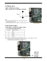
3-3 Battery Input
BAT1: 3V Battery hold 2pin
BAT1: Battery use Li 3V/220mAh (CR2032)
BAT1
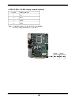
3-4 DC Power output
CPO1/CPO2: +12V/+5V DC voltage output
(1 X 4 pin 2.00mm Black wafer)
PIN NO
DESCRIPTION
1
+5V
2
GND
3
GND
4
+12V *
Note
:
1. DC in +12V by switch to DC-out v12V, so DC in need 12V input
2. Mating connector: JST B4B-PH-KL or compatible
3. Cable housing
:
JST PHR-4 or compatible
CPO1
pin1
CPO2
pin1
Note:
1. When board without Adaptor plug in, this board power RTC
consumption about 2.7uA
2. If adaptor always plug in RTC power consumption about 0.1uA
Содержание CI170A
Страница 8: ...3 2 1 3 1 2 3 Photo 1 Insert Unplug...
Страница 20: ...15 2 3 Dimension CI170A C...
Страница 117: ...112 8 Click Exit NOTE The path of the file For Windows 7 64 32 bit Windows 10 64 bit X driver sky_lake LAN Autorun exe...
Страница 119: ...114 Step 3 Choose ProgramAll Blocks and Do Not Check ROM ID Step 4 Click Flash Step 5 Click Exit and restart computer...


