


User Manual for PuraLev
®
2000SU
www.levitronix.com
PL-4034-00, Rev02, DCO# 20-144
37
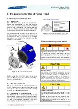
5.3
Mounting of Pump Head
5.3.1 Preparation
After removal of the pump head from its
packaging assure that no metallic part is
magnetically attaching. Specifically remove the
Protective Cup
, which comes delivered within the
packaging in order to magnetically fix the impeller
against movements and protect the pump head
bottom during handling and transportation.
Figure 39: Pump head with Protective Cup
Assure that the impeller speed is set to 0 rpm and
that the system is disabled.
5.3.2 Mounting Step 1: Insertion
To avoid squeezing the fingers by the magnetic
forces, do not directly insert the pump head into
the motor cavity and do not hold it on the bottom
side during insertion. First place the pump head
on the top of the motor by holding it below the
inlet fitting. Then move it sideways into the motor
cavity.
Figure 40: Insertion of pump head.
5.3.3 Mounting Step 2: Manual Screw Fixation
Align the pump head holes with the threads of the
pump head socket. Hand tighten the 4 screws.
5.3.4 Mounting Step 3: Ready-to-Use Check
Check that the pump head is properly aligned with
the
Pump Head Socket
.
5.4
Removal of Pump Head
5.4.1 Preparation
Set the speed to 0 rpm and disable the system.
After running at higher motor or liquid temperature
the pump head might stick to the motor due to
thermal expansion effects. Let the system cool
down before starting the removal procedure.
5.4.2 Removal Step 1: Remove the Screws
Remove the 4 manual screws.
5.4.3 Removal Step 2: Axial Removal
Smoothly remove the pump head following the
precautions and steps described in
Section 5.3.2
5.4.4 Removal Step 2: Protective Cup
It is recommended to attach the
Protective Cup
) to the pump head bottom in order
to minimize magnetic leakage fields surrounding
the impeller and hence reducing the tendency to
attract other magnetic parts.
5.5
Assembly into Circuit
The following points shall be considered, when
integrating the pump head into a single-use
circuit.
5.5.1 Usage of Protective Cup
During handling, assembling and transportation of
the pump head with the hydraulic circuit, it is
recommended to attach the
Protective Cup
(see
) with the integrated fixation disc to the
pump head bottom. The fixation disc holds the
impeller mechanically in place and reduces the
magnetic fields, which can attract other magnetic
parts during handling, sterilization and transport.
The protective cup avoids that the pump head
bottom is damaged.
5.5.2 Careful with Multiple Pump Heads
Take care to the magnetic forces of the
impellers when handling multiple pump heads
at the same time. Avoid two pump heads coming
together with force due to the magnetic attraction,
which might cause cracks.
5.5.3 Avoidance of Mechanical Stress
Avoid applying too much mechanical stress to
the pump head for example, by excessively
squeezing it with the other parts of the circuit into
packaging or an enclosed space of limited size,
or by applying too much tension or perpendicular
force to the fittings.
Integrated Fixation Disc
(for fixation of impeller)
Pump Head
DCP-2000
Protective Cup
Step 1a: Place the pump head on the
side of the top of the motor.
Step 1b: Move the pump head
sideways into the motor cavity.
To avoid squeezing the fingers,
do not hold the pump head on the
bottom side and do not directly
insert it into the motor cavity!


