3 INSTALLATION
5
3.2 Adding Meters and Sensors
3.2.1 Turn on the power supply. Confirm the green Alive LED is blinking about once per
second. Disconnect the power supply.
3.2.2 Verify that the device is recognized by LCC or the EMB Hub.
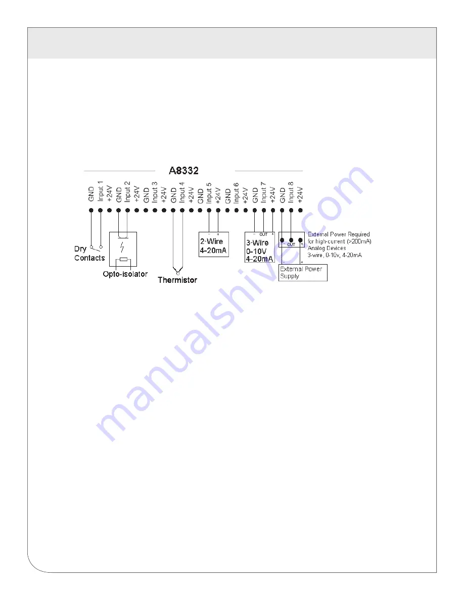
3.2.3 Disconnect the power. Attach the pulse or analog input lines to the pulse terminals. Each
input has a GND, Input#, and +24V terminal.
3.3 Powering up the Device
3.3.1 Reconnect power to the device. The green “Alive” LED should start to blink approximately once
per second.
3.3.2
The yellow RS485 TX and RX LEDs will blink for local Modbus activity.
3.3.3 For each input, you MUST configure the input mode register. The mode register sets up the input for
4-20mA, 0-10V, pulse, or resistance type sensors. The default mode is “unconfigured”.
(Choose only one method below)
3.3.3.1
On the EMB Hub device configuration page, select configure point. Pick the appropriate mode
from the dropdown list. You will need to configure each pulse input with a Name, Engineering
Unit, and Multiplier.
3.3.3.2
Using the Obvius Config Console software, select the A8332 from the list, and choose the input
mode from the dropdown list. Be sure to click the “Save” button at the bottom of the page.
3.3.4 After configuring the input mode, the red input status LEDs will show information for each input
depending on the configured mode of the input. Input status LEDs are adjacent to the corresponding
input screw terminals.
3.3.5 For inputs configured for pulse, pulse-kyz, and status, the LED will turn on when the contact is closed.
3.3.6 For 4-20mA, 0-10V modes, the LED will show off-scale-high by blinking fast (2x second)
3.3.7 For 4-20mA and Resistance mode, the LED will show a broken wire alarm with a blink-blink-off pattern.
3.3.8 For unconfigured inputs, the LED will be off.
WEB
VERSION
Содержание A8332
Страница 1: ...DG 004 A8332 00A ModbusTM Flex I O Module Cat No A8332 Quick Start Guide WEB VERSION...
Страница 2: ...WEB VERSION...
Страница 7: ...WEB VERSION...
Страница 8: ...DG 004 A8332 00A WEB VERSION...


