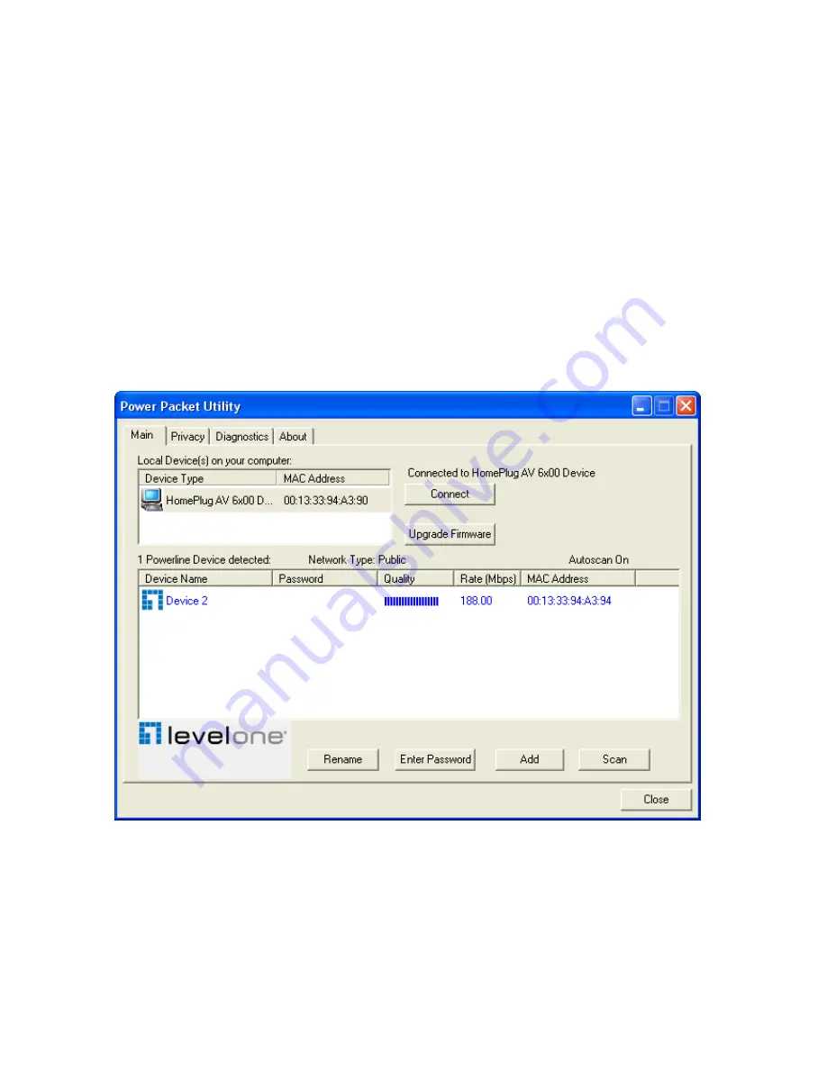
LevelOne PLI-3510 Скачать руководство пользователя страница 11


The 

Main 

screen provides a list of all powerline devices logically connected to the computer 

when the utility is  running.The 

top panel 

shows all local HomePlug devices connected to the 

computer’s NIC (Network Interface Card). In  most cases, only one device will be seen. In 

situations where there are more than one local device being connected, such as a USB or an 

Ethernet adapter, the user can select the local device by clicking on it and then click the 

Connect 

button to its right. The status area above the button indicates that your PC is connected to that 

same device. Once connected to the local device, the utility will automatically scan the power line 

periodically for any other HomePlug devices. If no local HomePlug devices are discovered, the 

status area above the connect button will indicate with a message ‘NO HOMEPLUG ADAPTERS 

DETECTED’. 

Figure 3-2


illustrates the presence of two local devices connected locally to the computer. 


Figure 3-2: Multiple Local Device Connection 


The 

lower panel 

displays all the HomePlug remote devices, discovered on the current logical 

network. The total number of remote devices connected on the same network can be found on 

top of the Remote device panel. The Network type (Public or Private) is also displayed based on 

the network status of the local device. The scan status option is displayed on the top right corner 

Содержание PLI-3510

Страница 1: ...LevelOne PLI 3510 200Mbps Powerline Adapter with Mains Pass Through User Manual ...

Страница 2: ...nts 1 Chapter 2 Installation Uninstallation 2 2 1 Installing Powerline Device 2 2 2 Installation of Powerline Utility 3 2 3 Uninstallation of Configuration Utility 7 3 1 Main Tab 8 3 2 Privacy Screen 14 3 3 Diagnostics Screen 15 3 4 About Screen 16 Chapter 4 Reset and Network ID Buttons Setting 17 4 1 Reset Button 17 4 2 Network ID Button 17 ...

Страница 3: ...equency 4 3 MHz 20 9 MHz Security 128 bits AES encryption IEEE802 3 10Base T IEEE802 3U 100Base TX 1 3 LED Indicators The Powerline Ethernet Adaptor has three LEDs indicator Turn on when connected to AC power supply Turn on when detected and connected with another HomePlug adaptor within the network Turn on when connected to the Ethernet card of the computer or Ethernet Hub Switch 1 4 Package Cont...

Страница 4: ...your PC s Ethernet port to the Powerline Ethernet Adapter s LAN Ports and connect the supplied RJ45 Ethernet cable from your xDSL Cable Modem s Ethernet port to the Powerline Ethernet Adapter s LAN Ports 3 Connect the Powerline Ethernet Adapter to your wall mounted power outlet 4 Check if the PLC LED of Powerline Ethernet Adapter is ON the Powerline Ethernet Adapter is connected and suitable for I...

Страница 5: ...ing this utility 1 In order to install insert Configuration Utility CD ROM into the computer s CD ROM drive The program shall run automatically Alternatively this can also be done manually by double clicking the autorun exe file on the CD 2 For Windows 7 Vista User only for Security reasons Windows 7 Vista requires the installer program to have administrator privileges so the new policy called Use...

Страница 6: ...4 4 Click Setup button to continue 5 Click Next button to continue 6 Click I Agree Next button to continue ...

Страница 7: ...5 7 Click Next button to continue 8 Click Close button to exit ...

Страница 8: ...the utility icon on desktop 10 You can see your device working well The top panel of the screen shot shows a Homeplug device connected locally to your computer The bottom panel shows one device connected remotely to the computer running the utility ...

Страница 9: ...all the Configuration Utility go to the Control Panel of your system 2 Open the Add Remove Programs 3 Select and double click on the Powerline Utility in the Add Remove Programs Properties 4 Follow the on screen instructions to uninstall the Powerline Utility ...

Страница 10: ...he Utility will use a Graphical User Interface GUI with limited user selectable options 3 1 Main Tab In order to start the utility double click the utility icon on desktop Figure 3 1 shows the main screen of the Configuration Utility The top panel of the screen shot shows a HomePlug AV device connected locally to the host computer The bottom panel shows four devices connected remotely to the compu...

Страница 11: ...connected to the local device the utility will automatically scan the power line periodically for any other HomePlug devices If no local HomePlug devices are discovered the status area above the connect button will indicate with a message NO HOMEPLUG ADAPTERS DETECTED Figure 3 2 illustrates the presence of two local devices connected locally to the computer Figure 3 2 Multiple Local Device Connect...

Страница 12: ...ar in the lower panel Device Name column shows the default device name which may be user re defined A user can change the name by either using the rename button or by clicking on the name and editing in place An icon is usually shown with the name By default the icon is always accompanied by a device name MAC Address column shows the Remote device s MAC address ...

Страница 13: ...dialog box will appear as shown in Figure 3 3 to type the password The selected device name is shown above the password field and the password can be verified by hitting the OK button The Password field accepts the Device password in any case formats with or without dashed between them If a device was not found the user will be notified along with the suggestions to resolve common problems This pr...

Страница 14: ... the user to enter both a device name and the password If a device was not found the user will be notified and suggestions to resolve common problems will be presented Figure 3 4 Add Remote Device Note The device must be present on the power line plugged in in order for the password to be confirmed and added to the network If the device could not be located a warning message will be shown ...

Страница 15: ...ug devices connected to the Powerline network By default the utility automatically scans every few seconds and updates the display screen A typical screen after naming and supplying passwords might appear as in Figure 3 5 Figure 3 5 Main Screen of the Configuration Utility ...

Страница 16: ...n HomePlugAV will show the network type on the main screen as Private Figure 3 6 Privacy Screen The Set Local Device Only button can be used to change the network name network password of the local device If a new network password is entered all the devices seen on the Main panel prior to this will be no longer present in the new network effectively making the local devices not to communicate to t...

Страница 17: ...e present on the host computer which were used to communicate over HomePlug on the Powerline network It shall include the following Operating System Platform Version Host Network Name User Name MAC Address of all NICs Network interface card connected to the host Identify versions of all Driver DLLs and Libraries used NDIS and optionally HomePlug chipset manufacturer name MAC Firmware Version MAC a...

Страница 18: ...rom the diagnostics screen Device Alias Name Device MAC Address Device Password Device Last known rate Device Last Known Network name HomePlug chipset manufacturer name Date device last seen on the network MAC Firmware Version The diagnostics information displayed may be saved to a text file for later use or can be printed for reference for a technical support call Devices which are not part of th...

Страница 19: ...ff when the device is in reset process 4 2 Network ID Button The HomePlug AV powerline communication devices can form multiple logical networks over a common powerline or coax medium There are many situations when it is desirable to add new devices to or remove old devices from a HomePlug AV logical network Push this button to accomplish using HomePlug AV Simple Connect Technology Network ID Butto...

Страница 20: ...on on the second device for less than 3 seconds The button on the second device must be pressed within 1 minute by default however the interval is programmable 4 Wait for connection to complete and the PLC LED will be ON The PWR LED on both devices will flash evenly at 1 second intervals until the operation succeeds or fails It will illuminate steadily on successful completion If an error occurs t...

Страница 21: ...the adder will flash unevenly until the Network ID button on the adder is pressed again or the joiner is reset by pressing the Network ID button for more than 10 seconds as described in Case 3 The join operation can be cancelled by pressing the Network ID button on the first device again for less than 3 seconds instead of pressing the Network ID button on the second device If you press Network ID ...

Страница 22: ...n on the leaver for at least 10 seconds The device will reset and restart with a random NMK 2 Wait for reset to complete and the PLC LED will be OFF The PWR LED on the leaver will momentarily extinguish during reset flash during restart then illuminate steadily No errors can occur Once the process completes the user may disconnect the device from the medium or join it to another logical network on...

Страница 23: ...peration in which an adder device in the network remains in the adder state for an extended period allowing additional joiners to be added in turn This lets you press the adder Network ID button once then press each joiner Network ID button in turn If Network ID buttons are pressed on two or more joiners only the first one will respond The second will not This makes timing important ...

Отзывы: