(BRANCH CIRCUIT)
WIRING
To connect motor for proper voltage and rotation, refer to connection diagram on nameplate or inside terminal/conduit box. If power factor
correction capacitors are used for individual motor power factor correction, do not exceed maximum recommended value.
All aspects of the installation must conform to the requirements of the NEC, including Article 430 (Motor Circuits and Controllers), and all
local codes. Wherever possible, each motor should be powered from a separate circuit of adequate capacity to keep voltage drop to a minimum during
starting and running. Increase wire size where motor is located a distance from the power source. Wire size must be adequate to minimize voltage drop
during starting and running. Refer to Tables A and B for suggested wire sizes. Distances shown are one-way between source and load. Portable cords, if
used, should be as short as possible to minimize voltage drop. Long or inadequately sized cords, especially on hard starting loads, can cause motor
failure. Insulate and protect motor lead connections to prevent cut-through from sharp edges and vibration. Tape wire nuts to prevent loosening. All
electrical connections in system must be secure to prevent voltage drop and localized heating.
Determine direction of rotation before connecting driven equipment to prevent damage. Remove shaft key if motor is to be operated at no-
load. On three phase motors, interchange any two line leads (not motor leads) to reverse rotation. On air compressors, rotation of flywheel should direct
air towards the cylinders. Look for rotational arrow on flywheel.
All motors must be securely and adequately grounded by wiring with a grounded, metal-clad raceway system, using a separate ground bond
wire connected to bare metal on the motor frame, or other suitable means. Refer to NEC Article 250 (Grounding) for additional information.
Explosion-proof motors incorporating overtempature thermostats should be controlled with a magnetic starter. The thermostat circuit must be
wired in series with the holding coil circuit, as shown on tag or nameplate on motor, to remove power from the starter coil if motor overheats.
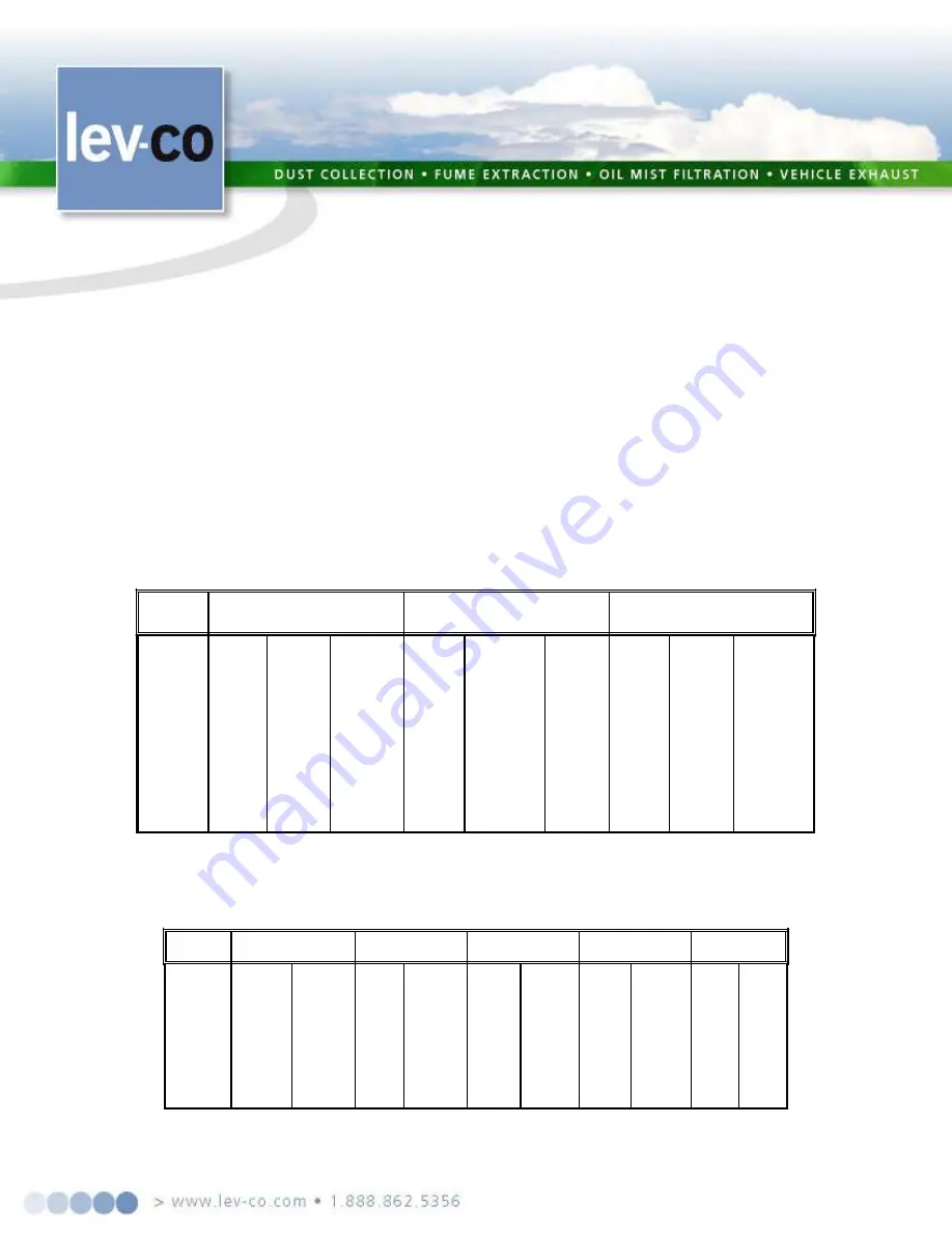
TABLE A - MINIMUM WIRE SIZES FOR THREE-PHASE MOTORS
[*]Type S, SO, SJ, SJO, etc. flexible cable wire sizes. See NEC Article 400 for ampacity
.
Note:
Above wire sizes based on approximate 5% voltage drop during starting; copper conductors; and 75°C type TH, THW, RH, RHW, etc. insulation. For aluminum
wire, increase two wire size steps minimum. See NEC Article 310 for ampacities of aluminum conductors and 60°C type RUW, T, etc. insulation
.
TABLE B - MINIMUM WIRE SIZES FOR SINGLE-PHASE MOTORS
[*] Type S, SO, SJ, SJO, etc. flexible cable wire sizes. See NEC Article 400 for ampacity.
Note:
Above wire sizes based on approximate 5% voltage drop during starting; copper conductors;and 75°C type TH, THW, RH, RHW, etc. insulation. For aluminum wire,
increase two wire size steps minimum. See NEC Article 310 for ampacities of aluminum conductors and 60°C type RUW, T, etc. insulation.
Page:
14/15 .
MOT0R
HP
25
FT
115V
230V
50
FT
115V
230V
100
FT
115V
230V
150
FT
115V
230V
200
FT
115V
230V
1/8
1/6
1/4
1/3
1/2
3/4
1
1½
2
3
14(16)*
14
14
14
14
12
10
10
8
8
14(18)*
14(18)*
14(18)*
14(18)*
14(18)*
14(18)*
14(16)*
14(16)*
14
10
14
12
12
10
10
8
8
6
6
4
14(18)*
14(18)*
14(18)*
14(16)*
14(16)*
14
14
12
12
10
10
10
8
8
8
6
4
4
3
2
14(16)*
14(16)*
14
14
14
12
10
10
8
8
10
8
6
6
6
4
4
2
2
1/0
14(16)*
14
12
12
12
10
8
8
6
6
8
6
6
4
4
3
2
1
1/0
2/0
14
12
12
10
10
8
8
6
6
4
MOTOR
HP
25 FT
TO
50 FT
200V
230V
460V
100 FEET
200V
230V
460V
150 FT
TO
200 FT
200V
230V
460V
1/8
1/6
1/4
1/3
1/2
3/4
1
1½
2
3
14(18)*
14(18)*
14(18)*
14(18)*
14(16)*
14
14
12
12
10
14(18)*
14(18)*
14(18)*
14(18)*
14(18)*
14(16)*
14(16)*
14
12
12
14(18)*
14(18)*
14(18)*
14(18)*
14(18)*
14(18)*
14(18)*
14(18)*
14(18)*
14(18)*
14(18)*
14(18)*
14(16)*
14(16)*
14
12
10
10
8
8
14(18)*
14(18)*
14(18)*
14(16)*
14
14
12
10
10
8
14(18)*
14(18)*
14(18)*
14(18)*
14(18)*
14(18)*
14(18)*
14(16)*
14(16)*
14
14(16)*
14(16)*
14
12
10
8
8
6
6
4
14(18)*
14(16)*
14
14
12
10
10
8
6
6
14(18)*
14(18)*
14(18)*
14(18)*
14(18)*
14(16)*
14
14
12
12
MOTOR WIRING GUIDE


