


Page A6
16. Remove the packing and backup ring from the valve body.
17. Thoroughly clean and inspect the valve components.
Replace all damaged parts.
E. VALVE REASSEMBLY
NOTE: When a hard (all metal) seat ring is to be the seat ring
it should be lapped. Perform the steps in the SEAT RING
LAPPING Section of this Instruction Manual before beginning
REASSEMBLY. (See page A7).
1.
Coat the inside and outside diameters of the lower guide
bearing with a lubricant, then install it in the valve body.
2.
Coat the inside and outside diameters of the upper guide
bearing with a lubricant, then install it on the valve shaft.
3.
Coat the valve shaft splines with a lubricant.
4.
While holding the plug inside the body, push the shaft
and upper guide bearing into place.
5.
Slide the backup ring and the new packing down the
valve shaft and into the packing chamber in the
sequence shown in Figure 3, Page A5, being sure to use
the proper lubricant if required. Then slide the packing
gland into place.
6.
While holding the packing gland clamp inside the
actuator yoke (with ball bearings), slide the packing
gland clamp and yoke together onto the valve shaft so
the slots in the packing gland clamp slide over two of the
studs.
7.
Secure the yoke to the valve with two nuts.
8.
Screw nuts on the studs to pull the packing gland clamp
down; tighten the nuts finger tight plus 1/2 turn. They will
need to be re-tightened after the valve is pressurized.
9.
For valves with service temperature of 400°F or greater,
a .005 inch gap between the plug and bottom bushing
should be adjusted, using a feeler gauge and the set
screws on top of the yoke. For all other valves snug set
screws to remove any gap between bearings and plug.
Plug should rotate freely in either case.
10. If the pipe plug was removed, coat the threads with flow
media compatible pipe compound and reinstall.
11. Lightly lubricate the beveled edge of the seat ring, then
apply a lubricant to a 1/4” wide band around the
circumference along both edges of the set ring O.D.
12. Place the seat ring into the body with the beveled edge
against the plug.
13. Coat the seat ring retainer threads with an anti-seize
compound, then install it in the body. Tighten only finger
tight.
14. Open and close the plug to align the seat to the plug and
body seating surfaces in the body. Leave the plug in the
closed position with the seat ring having both plug
contact and body contact.
15. Tighten the seat ring retainer to the torque specified in
Table A.
16. Open the valve until the plug does not contact the seat.
17. Re-torque the seat ring retainer per Table A.
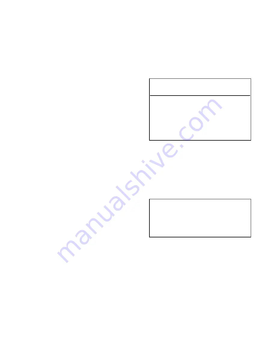
K-MAX SEAT RETAINER TORQUES
TABLE A
18. The seat ring retainer should rotate less than 20 degrees
after initial torquing (Step 16); retainer movement greater
than 20 degrees may indicate problems that could result
in seat leakage.
19. Mount the actuator on the valve as described in the
Actuator Installation Section of the Actuator Instruction
Manual.
20. Test the seat by applying low pressure (50 PSIG) to the
seat side of the body with the valve in the closed
position. If seat leakage occurs, remove the retainer and
seat ring from the body and begin the reassembly
procedure at Step 11 or lap the plug/seat as described
in the following seat ring lapping section. If leakage
persists after several disassembly/reassembly
sequences, contact your local Leslie/K & M
representative.
21. Thoroughly clean the valve to the standard dictated by
your process flow media.
WARNING
REVERSE ACTUATORS - APPLY AIR TO THE
ACTUATOR TO OPEN AND HOLD THE PLUG
POSITION BEFORE REMOVING THE SEAT
RETAINER.
VALVE
SEAT RETAINER TORQUE
SIZE
(ft. lbs.)
1
75
1.5
85
2
100
3
120
4
250
6
450
8
600