Leonton EG2-1604-SFP Series Скачать руководство пользователя страница 15

10 


Wiring the Fault Alarm Contact 

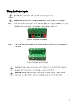
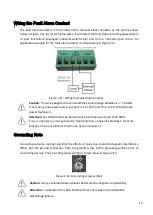
The fault alarm contact is in the middle of the terminal block connector as the picture shows 
below in Figure 2.11. By inserting the wires, it will detect the fault status including power failure 
or  port  link  failure  (managed  industrial  switch  only)  and  form  a  normally  open  circuit.  An 
application example for the fault alarm contact is shown below in Figure 2.11.


Figure 2.11: Wiring the Fault Alarm Contact


Caution: 

The wire gauge for the terminal block should range between 12 ~ 24 AWG.


If only using one power source, jumper Pin 1 to Pin 5 and Pin 2 to Pin 6 to eliminate 

power fault alarm.


Attention: 

Le calibre des fils du bornier doit être compris entre 12 et 24 AWG.


Si vous n'utilisez qu'une seule source d'alimentation, jumelez les broches 1 à 5 et les 

broches 2 à 6 pour éliminer l'alarme de panne de courant.


Grounding Note 

Grounding and wire routing help limit the effects of noise due to electromagnetic interference 
(EMI).  Run  the  ground  connection  from  the  ground  screw  to  the  grounding  surface  prior  to 
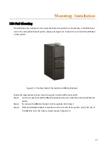
connecting devices. The grounding screw symbol is shown blow in Figure 2.12.


Figure 2.12: Grounding screw symbol


Caution: 

Using a shielded cable achieves better electromagnetic compatibility.


Attention: 

L'utilisation d'un câble blindé permet une meilleure compatibilité 

électromagnétique.


Содержание EG2-1604-SFP Series

Страница 1: ...LEONTON EG2 1604 SFP Series EG2 1604 SFP EG2 1604 SFP T User Manual...

Страница 2: ...t not limited to the implied warranties of merchantability and fitness for a particular purpose Leonton Technologies Co Ltd may make improvements and or changes to the product and or specifications of...

Страница 3: ...he grantee of this device could void the user s authority to operate the equipment D claration FCC Cet quipement a t test et reconnu conforme aux limites de la classe A pour les quipements num riques...

Страница 4: ...equired to take adequate measures CE Mark Avertissement Ceci est un produit de classe A Dans un environnement domestique ce produit peut tre utilis en pr sence d interf rences radio This document is t...

Страница 5: ...hysical Dimensions 3 Front Panel 4 Top View 4 LED Indicators 5 Ethernet Ports 6 Cabling 7 Wiring the Power Inputs 9 Wiring the Fault Alarm Contact 10 Grounding Note 10 Mounting Installation 11 DIN Rai...

Страница 6: ...ng an operating temperature of 10 C 65 C and another with a wide operating temperature of 40 C 75 C this series is designed to meet any needs for industrial automation application and harsh environmen...

Страница 7: ...tion sur l entr e d alimentation Fourniture par courant industriel homologu UL Les sp cifications mat rielles les ports les informations de c blage et l installation du c blage du convertisseur de m d...

Страница 8: ...3 Hardware Description Physical Dimensions Figure 2 1 below shows the physical dimensions of EG2 1604 SFP series W x H x D is 59mm x 142mm x 99mm Figure 2 1 Physical Dimensions...

Страница 9: ...Panel Top View Figure 2 3 below shows the top panel of the EG2 1604 SFP series switch that is equipped with one 6 pin removal terminal block connector for dual DC power inputs 12 48VDC Figure 2 3 Top...

Страница 10: ...Off Power input 2 is inactive Fault Red On Power input 1 or 2 is inactive Off Power input 1 and 2 are both functional LINK ACT SFP Port Green On Connected to network 1000Mbps Flashing Networking is a...

Страница 11: ...raight Through Cable Pin Number Signal Pin Number Signal Pin Number Signal Pin Number Signal 1 RX 3 TX 1 RX 1 TX 2 RX 6 TX 2 RX 2 TX 3 TX 1 RX 3 TX 3 RX 6 TX 2 RX 6 TX 6 RX Table 2 2 1000BASE T RJ 45...

Страница 12: ...hat complies with IEC 60825 1 and classified as Class 1 laser product Attention Veuillez utiliser un metteur r cepteur optique SFP conforme la norme CEI 60825 1 et class comme produit laser de classe...

Страница 13: ...hown below Step 1 Press the upper side of the LC connector from the transceiver and pull it out to release as shown below in Figure 2 7 Figure 2 7 Remove LC Connector Step 2 Push down the metal clasp...

Страница 14: ...tor as shown below in Figure 2 9 Figure 2 9 Power Terminal Block Step 2 Tighten the wire clamp screws to prevent the wires from loosening as shown below in Figure 2 10 Figure 2 10 Power Terminal Block...

Страница 15: ...n 1 to Pin 5 and Pin 2 to Pin 6 to eliminate power fault alarm Attention Le calibre des fils du bornier doit tre compris entre 12 et 24 AWG Si vous n utilisez qu une seule source d alimentation jumele...

Страница 16: ...ure 3 1 The Rear Side of the Switch and DIN Rail Bracket Follow the steps below to learn how to hang the industrial Ethernet switch Step 1 Use the screws to install the DIN Rail bracket on the rear si...

Страница 17: ...ull down the bracket on to the rail as shown below in Figure 3 3 Figure 3 3 Stable the Switch on DIN Rail Step 5 Check if the bracket is mounted tightly on the rail Step 6 To remove the industrial Eth...

Страница 18: ...strial Ethernet switch Step 3 Use the screws to screw the wall mounting bracket on the industrial Ethernet switch Step 4 Use the hook holes at the corners of the wall mounting bracket to hang the indu...

Страница 19: ...Wiring the Power Inputs section Please refer to the LED Indicators section for LED light indication Step 5 Prepare the twisted pair straight through category 5 cable for Ethernet connection Step 6 Ins...

Страница 20: ...st me int grant l quipement est de la responsabilit de l assembleur du syst me Caution This is an OPEN TYPE module and should be installed in a final safety enclosure characteristic Attention Il s agi...

Страница 21: ...which help to identity if any problems exist Please refer to the LED Indicators section for LED light indication If the power indicator LED does not turn on when the power cord is plugged in the user...

Отзывы: