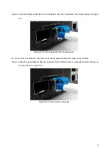
background image

13 

Wall Mounting 

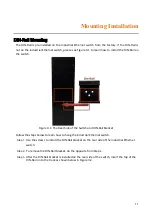
Follow the steps below to mount the industrial Ethernet switch using the wall mounting bracket 
as shown below in Figure 3.4.


Step 1. 

Remove the DIN-Rail bracket from the industrial Ethernet switch by loosening the screws.
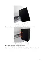
 

Step 2. 

Place the wall mounting brackets on the top and bottom of the industrial Ethernet switch.


Step 3. 

Use the screws to screw the wall mounting bracket on the industrial Ethernet switch.


Step 4. 

Use the hook holes at the corners of the wall mounting bracket to hang the industrial 

Ethernet switch on the wall.


Step 5. 

To remove the wall mount bracket, do the opposite from the steps above.


Figure 3.4: Remove DIN-Rail Bracket from the Switch


Below, in Figure 3.5 are the dimensions of the wall mounting bracket. 


Figure 3.5: Wall Mounting Bracket Dimensions


Содержание EG2-1202-SFP Series

Страница 1: ...Leonton EG2 1202 SFP Series EG2 1202 SFP EG2 1202 SFP T User Manual Version 1 0...

Страница 2: ...t not limited to the implied warranties of merchantability and fitness for a particular purpose Leonton Technologies Co Ltd may make improvements and or changes to the product and or specifications of...

Страница 3: ...the equipment off and on the user is encouraged to try to correct the interference by one or more of the following measures Reorient or relocate the receiving antenna Increase the separation between t...

Страница 4: ...ption 3 Physical Dimensions 3 Front Panel 4 Top View 4 LED Indicators 5 Ethernet Ports 6 Cabling 7 Wiring the Power Inputs 9 Wiring the Fault Alarm Contact 10 Mounting Installation 11 DIN Rail Mountin...

Страница 5: ...f 10 C 65 C and another with a wide operating temperature of 40 C 75 C this series is designed to meet any needs for industrial automation application and harsh environments Key Features Interface Per...

Страница 6: ...tion If the DC voltage is supplied by an external circuit please use a protection device on the power supply input Supply by UL Listed industrial use power The industrial Ethernet switch s hardware sp...

Страница 7: ...3 Hardware Description Physical Dimensions Figure 2 1 below shows the physical dimensions of EG2 1202 SFP series W x H x D is 46mm x 142mm x 99mm Figure 2 1 EG2 1202 SFP Series Physical Dimensions...

Страница 8: ...shown below in Figure 2 2 Figure 2 2 The Front Panel of EG2 1202 SFP Series Top View Figure 2 3 below shows the top panel of the EG2 1202 SFP series switch that is equipped with one 6 pin removal term...

Страница 9: ...t 2 is inactive Fault Red On Power input 1 or 2 is inactive Off Power input 1 and 2 are both functional SFP Port LINK ACT SPEED Green On Connected to network 1000Mbps Flashing Networking is active Off...

Страница 10: ...raight Through Cable Pin Number Signal Pin Number Signal Pin Number Signal Pin Number Signal 1 RX 3 TX 1 RX 1 TX 2 RX 6 TX 2 RX 2 TX 3 TX 1 RX 3 TX 3 RX 6 TX 2 RX 6 TX 6 RX Table 2 2 1000BASE T RJ 45...

Страница 11: ...t optical transceiver used in optical communications for both telecommunication and data communication applications To connect the transceiver and LC cable please follow below steps Step 1 Insert the...

Страница 12: ...ure 2 11 Figure 2 11 LC Connector to the Transceiver To remove the LC connector from the transceiver please follow the steps shown below Step 1 Press the upper side of the LC connector from the transc...

Страница 13: ...Insert the positive and negative wires into the PWR1 V1 V1 and PWR2 V2 V2 contacts on the terminal block connector as shown below in Figure 2 14 Figure 2 14 Power Terminal Block Step 2 Tighten the wi...

Страница 14: ...luding power failure or port link failure managed industrial switch only and form a normally open circuit An application example for the fault alarm contact is shown below in Figure 2 16 Figure 2 16 W...

Страница 15: ...ure 3 1 The Rear Side of the Switch and DIN Rail Bracket Follow the steps below to learn how to hang the industrial Ethernet switch Step 1 Use the screws to install the DIN Rail bracket on the rear si...

Страница 16: ...ull down the bracket on to the rail as shown below in Figure 3 3 Figure 3 3 Stable the Switch on DIN Rail Step 5 Check if the bracket is mounted tightly on the rail Step 6 To remove the industrial Eth...

Страница 17: ...ottom of the industrial Ethernet switch Step 3 Use the screws to screw the wall mounting bracket on the industrial Ethernet switch Step 4 Use the hook holes at the corners of the wall mounting bracket...

Страница 18: ...o the Mounting Installation section Step 4 Power on the industrial Ethernet switch and then the power LED light will turn on If you need help on how to wire power please refer to the Wiring the Power...

Страница 19: ...assist in identifying problems the switch can be easily monitored with the LED indicators which help to identity if any problems exist Please refer to the LED Indicators section for LED light indicat...

Отзывы: