


4
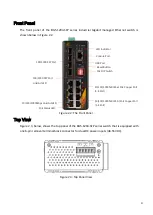
Front Panel
The front panel of the BG5-1204-SFP series industrial Gigabit managed Ethernet switch is
shown below in Figure 2.2.
Figure 2.2: The Front Panel
Top View
Figure 2.3, below, shows the top panel of the BG5-1204-SFP series switch that is equipped with
one 6-pin removal terminal block connector for dual DC power inputs (48-55VDC).
Figure 2.3: Top Panel View
LED Indicator
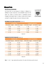
Console Port
USB Port
Reset Button
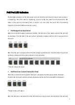
PoE Status LED
10/100/1000Mbps Link/Act LED
10/100/1000Tx RJ45 bt PoE Copper Port
(1-4 Port)
100/1000 SFP Port
100/1000 SFP Port
Link/Act LED
PoE DIP Switch
10/100/1000Tx RJ45 at PoE Copper Port
(5-8 Port)