background image

Commissioning

EDK10202EZ3 4.1

l

- 5 -

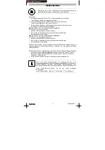
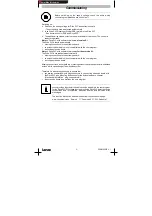
Before switching on the supply voltage, check the entire wiring
concerning completeness and short circuit.

Switching on:
4. Switch on the supply voltage for Drive PLC and extension board

- The extension board is detected automatically.

5. Load Drive PLC Developer Studio (DDS) project in the Drive PLC

- See documention for DDS and Drive PLC.

6. The additional inputs and outputs are now available for the control. The control is

ready for operation.

Note on Drive PLC with software version as of version 6.1:
The Drive PLC detects automatically

y

missing connections to the extension board.

y

an extension board which is not compatible with the user program.

y

a missing extension board.

Note on Drive PLC with software version earlier than version 6.1:
The Drive PLC does not detect automatically

y

missing connections to the extension board.

y

an extension board which is not compatible with the user program.

y

a missing extension board.

Missing connections, incompatibility or missing extension boards can result in undefined
actions which can endanger the machine/system.

Therefore it is absolutely necessary to ensure that

y

you always use two 26-pole plug connectors to connect the extension board with
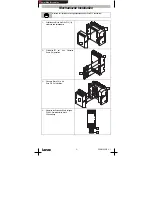
the Drive PLC (see Mounting Instructions for the Extension Board, chapter
“ Mechanical installation” , plug connectors

).

y

the extension board type matches the user program.

Lenze provides function blocks which can be loaded into the user program
for the Drive PLC. With these function blocks the Drive PLC detects missing
connections and incompatible extension boards and indicates error
messages.

The function blocks can be downloaded from the Lenze homepage:
www.Lenze.de (menu “ Service”

“ Downloads”

“ PLC Produkte” ).

Show/Hide Bookmarks

Содержание II EPZ-10202

Страница 1: ...2 digitale Ausgänge 011 012 Allgemeine Daten und Einsatzbedingungen Konformität CE Niederspannungsrichtlinie 73 23 EWG Approbationen UL 508C Underwriter Laboratories File No E132659 Power Conversion Equipment DC Versorgungsspannung Spannung extern 18 VDC 0 30 VDC 0 DC Versorgungsspannung Strom max 8 A bei max Belastung aller Ausgänge Klimatische Bedingungen Klasse 3K3 nach EN 50178 ohne Betauung m...

Страница 2: ...PLC abschalten c Schutzkappe von der Drive PLC 1a entfernen und aufbewahren A 1a d Stiftleisten auf das Extension Board 1b einsetzen B 1b e Extension Board 1b in die Drive PLC 1a einsetzen 1a 1b f Klemmen des Extension Board belegen PES HF Schirmabschluß durch PE Anbindung PES PES Show Hide Bookmarks ...

Страница 3: ...1 X2 X3 X4 Klemmen Belegung X1 Digitale Ausgänge X1 O5 X1 010 X2 Digitale Eingänge X2 I21 X2 I22 X2 Digitale Ausgänge X2 O11 X2 O12 DC Versorgungsspannung X2 24 X2 O24 X3 Digitale Eingänge X3 I15 X3 I20 X4 Digitale Eingänge X4 I9 X4 I14 Show Hide Bookmarks ...

Страница 4: ...C Versorgungsspannung 18 VDC 30 VDC Geschaltet über Not Aus an der Drive PLC X2 24 GND Bezugspotential X2 O11 Digitale Ausgänge LOW 0 V 4 V HIGH 13 V 30 V X2 O12 Ausgänge HIGH 13 V 30 V Belastbarkeit max 1 A X3 I15 Digitale Ei ä LOW 0 V 4 V G Digitale Eingänge LOW 0 V 4 V HIGH 13 V 30 V Eingangsstrom X3 I20 Eingangsstrom max 8 mA bei 24 V X4 I9 max 8 mA bei 24 V X4 I14 Hinweis y Achten Sie auf ein...

Страница 5: ...ehlende Verbindungen zum Extension Board y ein nicht zum Anwenderprogramm kompatibles Extension Board y ein fehlendes Extension Board Fehlende Verbindungen nicht kompatible oder fehlende Extension Boards können im Anwenderprogramm undefinierte Aktionen auslösen die die Maschine Anlage gefährden können Stellen Sie deshalb vor Inbetriebnahme einer Drive PLC mit Extension Board sicher daß y das Exten...

Страница 6: ...l inputs I21 I22 digital outputs 011 012 General data and application conditions Conformity CE Low Voltage Directive 73 23 EEC Approvals UL 508C Underwriter Laboratories File No E132659 Power Conversion Equipment DC supply voltage Voltage external 18 VDC 0 30 VDC 0 DC supply voltage Current max 8 A at max load of all outputs Climatic conditions Class 3K3 to EN 50178 without condensation average re...

Страница 7: ... PLC c Remove the protection cover from the Drive PLC 1a and keep it A 1a d Plug the plug connectors onto the Extension Board 1b B 1b e Connect the Extension Board 1b to the Drive PLC 1a 1a 1b f Assign the terminals of the Extension Board PES HF shield termination by PE connection PES PES Show Hide Bookmarks ...

Страница 8: ...overview X1 X2 X3 X4 terminals Assignment X1 Digital outputs X1 O5 X1 010 X2 Digital inputs X2 I21 X2 I22 X2 Digital outputs X2 O11 X2 O12 DC supply voltage X2 24 X2 O24 X3 Digital inputs X3 I15 X3 I20 X4 Digital inputs X4 I9 X4 I14 Show Hide Bookmarks ...

Страница 9: ...V X2 O24 DC supply voltage 18 VDC 30 VDC Connected via emergency off at the Drive PLC X2 24 GND reference potential X2 O11 Digital outputs LOW 0 V 4 V HIGH 13 V 30 V X2 O12 outputs HIGH 13 V 30 V Load capacity max 1 A X3 I15 Digital i LOW 0 V 4 V HIGH 13 V 30 V g ta inputs O 0 HIGH 13 V 30 V Input current max 8 X3 I20 Input current max 8 mA at 24 V X4 I9 mA at 24 V X4 I14 Note y Ensure a sufficien...

Страница 10: ...1 The Drive PLC does not detect automatically y missing connections to the extension board y an extension board which is not compatible with the user program y a missing extension board Missing connections incompatibility or missing extension boards can result in undefined actions which can endanger the machine system Therefore it is absolutely necessary to ensure that y you always use two 26 pole...

Страница 11: ...es 011 012 Caractéristiques générales et conditions d utilisation Conformité CE Directive Basse Tension 73 23 CEE Homologations UL 508C Underwriter Laboratories File No E132659 Power Conversion Equipment Alimentation CC Tension 18 VCC 0 30 VCC 0 externe Alimentation CC Courant 8 A maxi avec charge maxi sur toutes les sorties Humidité admissible Classe 3K3 selon EN 50178 sans condensation humidité ...

Страница 12: ...e capot de protection du Drive PLC 1a le conserver précieusement A 1a d Enficher les connecteurs à broches dans la carte d extension 1b B 1b e Enficher la carte d extension 1b dans le Drive PLC 1a 1a 1b f Affecter les bornes de la carte d extension PES terminaison blindage HF par raccordement PE PES PES Show Hide Bookmarks ...

Страница 13: ...1 X2 X3 X4 Bornier Affectation X1 Sorties numériques X1 O5 X1 010 X2 Entrées numériques X2 I21 X2 I22 X2 Sorties numériques X2 O11 X2 O12 Alimentation courant continu X2 24 X2 O24 X3 Entrées numériques X3 I15 X3 I20 X4 Entrées numériques X4 I9 X4 I14 Show Hide Bookmarks ...

Страница 14: ...ntinu 18 VCC 30 VCC Coupée via arrêt d urgence sur le Drive PLC X2 24 GND potentiel de référence X2 O11 Sorties numériques BAS 0 V 4 V HAUT 13 V 30 V X2 O12 numériques HAUT 13 V 30 V Charge maxi admissible 1 A X3 I15 Entrées é i BAS 0 V 4 V HAUT 13 V 30 V t ées numériques S 0 HAUT 13 V 30 V Courant d entrée X3 I20 Courant d entrée 8 mA maxi pour 24 V X4 I9 8 mA maxi pour 24 V X4 I14 Remarque impor...

Страница 15: ... n est pas relié à la carte d extension y si la carte d extension n est pas compatible avec le programme utilisateur y si la carte d extension est débranchée Une mauvaise liaison une carte d extension non compatible ou manquante peuvent provoquer des actions indéfinies dans le programme utilisateur qui peuvent mettre en danger la machine l installation ou les personnes Avant la mise en service d u...

Отзывы: