6
Elektrische Installation
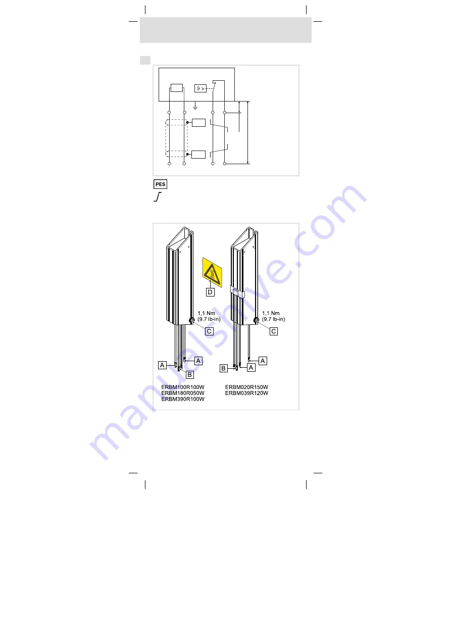
Montageschritte
EDKRBM390R DE/EN/FR/ES/IT 3.1
20
H1_E_INST−Mech Installation Aufkleber
Variante 2: Mit Leitungsverlängerung
R
B
<5m
<
0.1
m
PE
PES
PES
ERBMXXX014
HF−Schirmabschluss durch großflächige PE−Anbindung
Verdrillte Leitungen
Montageschritte
ERBM82−004


