


Safety engineering
Device modules
Mission time
27
EDS94AYAF EN 1.0
1.2.4.3
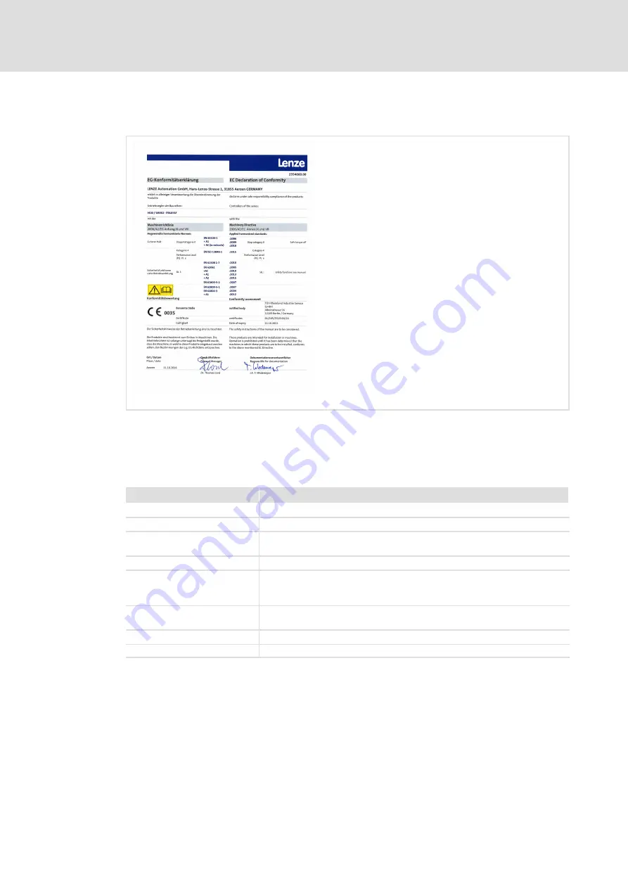
EC Declaration of Conformity
eulep...2354660
Fig. 1−4
EC Declaration of Conformity
The EC type examination was carried out by ’TÜV Rheinland (Group)’ and confirmed with
a certificate.
ƒ
SM302 V1.0
Contents
Specifications
Test institute
TÜV Rheinland Industrie Service GmbH, A−FS range
Test report
968/FSP 1323.00/16
Test fundamentals
EN 60204−1, EN 61800−3, EN 61508 Part 1−7, EN ISO 13849−1, EN 62061,
EN 61800−5−2, EN 61800−5−1
Object to be examined
SM302, type E94AYAF of the Servo Drives 9400 series
Test result
The module meets the requirements according to
l
EN 61508, SIL 3
l
EN ISO 13849−1, category 4/PL e
Special conditions
The safety instructions in the corresponding user documentation must be
observed.
Place of issue
Cologne
Issue date
11.10.2016