


Page 16
D- Gas Pressure Adjustment
Gas Flow (Approximate)
TABLE 6
GAS METER CLOCKING CHART
Unit
Seconds for One Revolution
Natural
LP
1 cu ft
Dial
2 cu ft
Dial
1 cu ft
Dial
2 cu ft
DIAL
-045
80
160
200
400
-070
55
110
136
272
-090
41
82
102
204
-110
33
66
82
164
-135
27
54
68
136
Natural-1000 btu/cu ft LP-2500 btu/cu ft
Furnace should operate at least 5 minutes before check
ing gas flow. Determine time in seconds for
two
revolu
tions of gas through the meter. (Two revolutions assures a
more accurate time.)
Divide by two
and compare to time
in table 6 below. If manifold pressure matches table 8 and
rate is incorrect, check gas orifices for proper size and re
striction. Remove temporary gas meter if installed.
NOTE
- To obtain accurate reading, shut off all other gas
appliances connected to meter.
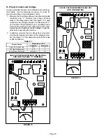
Manifold Pressure Measurement
1 - Remove the threaded plug from the outlet side of the
gas valve and install a field-provided barbed fitting.
Connect to a test gauge to measure manifold pres
sure.
2 - Start unit and allow 5 minutes for unit to reach steady
state.
3 - While waiting for the unit to stabilize, observe the
flame. Flame should be stable and should not lift from
burner. Natural gas should burn blue.
4 - After allowing unit to stabilize for 5 minutes, record
manifold pressure and compare to value given in table
8.
NOTE
- Shut unit off and remove manometer as soon as an
accurate reading has been obtained. Take care to remove
barbed fitting and replace threaded plug. Re-fire unit and
check for gas leaks. Seal any leaks if found.
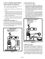
E- Proper Combustion
Furnace should operate a minimum 15 minutes with cor
rect manifold pressure and gas flow rate before checking
combustion. Take combustion sample beyond the flue out
let and compare to the tables below. The maximum carbon
monoxide reading should not exceed 100 ppm.
TABLE 7
ML180UHA
Unit
CO
2
%
For Nat
CO
2
%
For L.P.
-070
6.3 - 7.8
7.0 - 9.0
-090
-110
-135
F- High Altitude
The manifold pressure may require adjustment and com
bustion air pressure switch may need replacing to ensure
proper combustion at higher altitudes. Refer to table 8 for
manifold pressure and table 9 for pressure switch change
and gas conversion kits.
IMPORTANT
For safety, shut unit off and remove manometer as
soon as an accurate reading has been obtained.
Take care to replace pressure tap plug.
TABLE 8
Manifold Pressure Settings at all Altitudes
Model
Input Size
Gas
0-610 m*
(0-2000 ft)
611-914 m*
(2001-3000 ft.)
915-1219 m*
(3001-4000 ft)
1220-1524 m*
(4001-5000 ft.)
1525-1981 m*
(5001-6500 ft)
Line Pressure
kPa
Min
Max
All Models
Nat
0.87
0.72
0.67
0.62
0.87
1.13
3.23
LP/propane
2.30
2.30
2.19
2.12
2.30
2.75
3.23
* See table 9 for proper high altitude gas conversion kit.
TABLE 9
Pressure Switch and Gas Conversion Kits at all Altitudes
Model
Input Size
High Altitude Pressure Switch Kit
High Altitude
Natural Gas Burner
Orifice Kit
Natural Gas to LP/Propane
Change Over Kit
LP/Propane to
Natural Gas
Change Over Kit
0-610 m
(0-2000 ft)
611-1219 m
(2001-4000 ft)
1220-1981 m
(4001-6500 ft)
1525-1981 m
(5001-6500 ft)
0-1524 m
(0-5000 ft)
1525-1981 m
(5001-6500 ft)
1-1524 m
(1-5000 ft)
070
No Change
80W51
80W56
73W37
11K15
97W04
96W95
090
80W51
80W56
110
80W51
80W56
135
No Change
80W51


