Lenovo YOGA 3-1170 Скачать руководство пользователя страница 38

34

YOGA 3-1170 Hardware Maintenance Manual

1020 Battery pack

For access, remove this FRU:

• 

“1010 Base cover” on page 32

 DANGER

Only use the battery specified in the parts list for your computer. Any other battery 

could ignite or explode. 

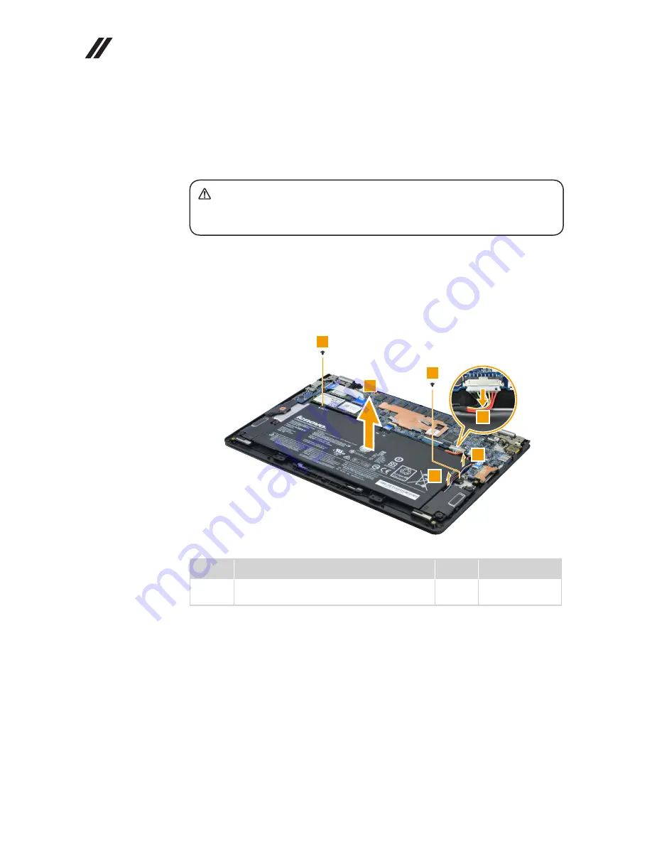
Figure 2. Removal steps of battery pack

Unplug the battery connector 

1

 and remove the screws 

2

. Release the 

speaker cable from the cable guides in the direction shown by arrows 

3

. Then 

remove the battery pack 

4

.

2

2

4

3

3

1

Step

Screw (quantity)

Color

Torque

2

M1.98 × 3 mm, Phillips-head, nylok-coated (2)


BATT module---Logic upper

Black

1.5~2.0 kgf*cm

When installing:

 Make sure that the battery connector is attached firmly.

Содержание YOGA 3-1170

Страница 1: ...YOGA 3 YOGA 3 1170 Hardware Maintenance Manual ...

Страница 2: ...ices on page 67 First Edition Sep 2014 Copyright Lenovo 2014 All rights reserved LIMITED AND RESTRICTED RIGHTS NOTICE If data or software is delivered pursuant a General Services Administration GSA contract use reproduction or disclosure is subject to restrictions set forth in Contract No GS 35F 05925 2014 Lenovo ...

Страница 3: ... Hard disk password 24 Supervisor password 24 Power management 25 Screen blank state 25 Putting the computer to sleep or shutting it down 25 Putting your computer to sleep 25 Shutting down the computer 26 YOGA 3 1170 27 Specifications 27 Status indicators 28 Keyboard function keys 29 FRU replacement notices 30 Screw notices 30 Removing and replacing an FRU 31 1010 Base cover 32 1020 Battery pack 3...

Страница 4: ...n guidelines and safety information required for servicing computers The product specific section includes service reference and product specific parts information Important This manual is intended only for trained servicers who are familiar with Lenovo products Use this manual to troubleshoot problems effectively Before servicing a Lenovo product make sure to read all the information under Safety...

Страница 5: ...ith before you service a YOGA 3 1170 computer General safety on page 2 Electrical safety on page 3 Safety inspection guide on page 5 Handling devices that are sensitive to electrostatic discharge on page 6 Grounding requirements on page 6 Safety notices multilingual translations on page 7 Laser compliance statement on page 14 ...

Страница 6: ...ce away from all personnel while you are servicing the machine Keep your toolcase away from walk areas so that other people will not trip over it Do not wear loose clothing that can be trapped in the moving parts of the machine Make sure that your sleeves are fastened or rolled up above your elbows If your hair is long fasten it Insert the ends of your necktie or scarf inside clothing or fasten it...

Страница 7: ...x in the off position If you need to work on a machine that has exposed electrical circuits observe the following precautions Ensure that another person familiar with the power off controls is near you Attention Another person must be there to switch off the power if necessary Use only one hand when working with powered on electrical equipment keep the other hand in your pocket or behind your back...

Страница 8: ... a plastic dental mirror The surface is conductive such touching can cause personal injury and machine damage Do not service the following parts with the power on when they are removed from their normal operating places in a machine Power supply units Pumps Blowers and fans Motor generators and similar units This practice ensures correct grounding of the units If an electrical accident occurs Caut...

Страница 9: ...e or missing hardware To determine whether there are any potential unsafe conditions use the following checklist at the beginning of every service task Begin the checks with the power off and the power cord disconnected Checklist 1 Check exterior covers for damage loose broken or sharp edges 2 Turn off the computer Disconnect the power cord 3 Check the power cord for a A third wire ground connecto...

Страница 10: ...to eliminate static on your body Prevent the part from touching your clothing Most clothing is insulative and retains a charge even when you are wearing a wrist strap Use the black side of a grounded work mat to provide a static free work surface The mat is especially useful when handling ESD sensitive devices Select a grounding system such as those listed below to provide protection that meets th...

Страница 11: ... Austausch der Computer wieder angeschlossen wird muß sichergestellt werden daß keine Schrauben Federn oder andere Kleinteile fehlen oder im Gehäuse vergessen wurden Der Computer muß geschüttelt und auf Klappergeräusche geprüft werden Metallteile oder splitter können Kurzschlüsse erzeugen Prima di accendere l elaboratore dopo che é stata effettuata la sostituzione di una FRU accertarsi che tutte l...

Страница 12: ...n Sie darf nicht zerlegt wiederaufgeladen kurzgeschlossen oder Feuer oder Wasser ausgesetzt werden Bei der Entsorgung die örtlichen Bestimmungen für Sondermüll beachten Beim Ersetzen der Bereitschafts oder Systembatterie nur Batterien des Typs verwenden der in der Ersatzteilliste aufgeführt ist Der Einsatz falscher Batterien kann zu Entzündung oder Explosion führen Alcune batterie di riserva conte...

Страница 13: ...eschlossen oder Feuer oder Wasser ausgesetzt werden Bei der Entsorgung die örtlichen Bestimmungen für Sondermüll beachten Beim Ersetzen der Batterie nur Batterien des Typs verwenden der in der Ersatzteilliste aufgeführt ist Der Einsatz falscher Batterien kann zu Entzündung oder Explosion führen La batteria contiene piccole quantità di nichel Non smontarla gettarla nel fuoco o nell acqua né cortoci...

Страница 14: ...s Typs dürfen nicht aufgeladen zerlegt über 100 C erhitzt oder verbrannt werden Auch darf ihr Inhalt nicht mit Wasser in Verbindung gebracht oder der zur richtigen Polung angebrachte Verbindungsstecker entfernt werden Bei der Entsorgung die örtlichen Bestimmungen für Sondermüll beachten Beim Ersetzen der Batterie nur Batterien des Typs verwenden der in der Ersatzteilliste aufgeführt ist Der Einsat...

Страница 15: ...irm besteht aus Glas und kann zerbrechen wenn er unsachgemäß behandelt wird oder der Computer auf den Boden fällt Wenn der Bildschirm beschädigt ist und die darin befindliche Flüssigkeit in Kontakt mit Haut und Augen gerät sollten die betroffenen Stellen mindestens 15 Minuten mit Wasser abgespült und bei Beschwerden anschließend ein Arzt aufgesucht werden Nel caso che caso l LCD si dovesse rompere...

Страница 16: ...tery can produce enough current to burn personnel or combustible materials Bien que le voltage des batteries principales soit peu élevé le court circuit ou la mise à la masse d une batterie peut produire suffisamment de courant pour brûler des matériaux combustibles ou causer des brûlures corporelles graves Obwohl Hauptbatterien eine niedrige Spannung haben können sie doch bei Kurzschluß oder Erdu...

Страница 17: ...et déconnectez tous les cordons d interface Die Stromzufuhr muß abgeschaltet alle Stromkabel aus der Steckdose gezogen der Akku entfernt und alle Verbindungskabel abgenommen sein bevor eine FRU entfernt wird Prima di rimuovere qualsiasi FRU spegnere il sistema scollegare dalle prese elettriche tutti i cavi di alimentazione rimuovere la batteria e poi scollegare i cavi di interconnessione Antes de ...

Страница 18: ...mance of procedures other than those specified herein might result in hazardous radiation exposure O uso de controles ajustes ou desempenho de procedimentos diferentes daqueles aqui especificados pode resultar em perigosa exposição à radiação Pour éviter tout risque d exposition au rayon laser respectez les consignes de réglage et d utilisation des commandes ainsi que les procédures décrites Werde...

Страница 19: ...luz Rayonnement laser si carter ouvert Évitez de fixer le faisceau de le regarder directement avec des instruments optiques ou de vous exposer au rayon Laserstrahlung bei geöffnetem Gerät Nicht direkt oder über optische Instrumente in den Laserstrahl sehen und den Strahlungsbereich meiden Kinyitáskor lézersugár Ne nézzen bele se szabad szemmel se optikai eszközökkel Kerülje a sugárnyalábbal való é...

Страница 20: ...ed on the customer support site http support lenovo com Strategy for replacing FRUs Before replacing parts Make sure that all software fixes drivers and BIOS downloads are installed before replacing any FRUs listed in this manual After a system board is replaced ensure that the latest BIOS is loaded to the system board before completing the service action To download software fixes drivers and BIO...

Страница 21: ...onfiguration settings using the View Configuration option then when service has been completed verify that those settings remain in effect Strategy for replacing a hard disk drive Always try to run a low level format before replacing a hard disk drive This will cause all customer data on the hard disk to be lost Make sure that the customer has a current backup of the data before performing this ac...

Страница 22: ...ance well before the implementation date and expects its suppliers to be ready to support Lenovo s requirements and schedule in the EU Products sold in 2005 and 2006 will contain some RoHS compliant FRUs The following statement pertains to these products and any product Lenovo produces containing RoHS compliant FRUs RoHS compliant FRUs have unique FRU part numbers Before or after the RoHS implemen...

Страница 23: ...ence might have been altered If you select an incorrect drive data or programs might be overwritten Replace an FRU only with another FRU of the correct model When you replace an FRU make sure that the machine model and the FRU part number are correct by referring to the FRU parts list An FRU should not be replaced just because of a single unreproducible failure Single failures can occur for a vari...

Страница 24: ...arranty by referring to the following list The following are not covered under warranty LCD panel cracked from the application of excessive force or from being dropped Scratched cosmetic parts Distortion deformation or discoloration of the cosmetic parts Plastic parts latches pins or connectors that have been cracked or broken by excessive force Damage caused by liquid spilled into the system Dama...

Страница 25: ...ter is used If the power on indicator does not turn on check the power cord of the AC adapter for correct continuity and installation If the computer does not charge during operation go to Checking operational charging To check the AC adapter follow the steps below 1 Unplug the AC adapter cable from the computer 2 Measure the output voltage at the plug of the AC adapter cable See the following fig...

Страница 26: ...that has less than 50 of the total power remaining when installed in the computer Perform operational charging If the battery status indicator or icon is not lit remove the battery pack and let it return to room temperature Reinstall the battery pack If the charge indicator or icon is still off replace the battery pack If the charge indicator is still not lit replace the system board ...

Страница 27: ...overy System In order to save application files and the initial backed up files of the system the hard disk in a Lenovo computer includes a hidden partition when it is shipped If you need to restore the system to the point of your first boot up just enter Lenovo OneKey Recovery System and run System Recovery For details of OneKey Recovery System see the User Guide for Lenovo OneKey Recovery system...

Страница 28: ...system administrator who can use it to get access to the hard disk drive even if the user has changed the user HDP Attention If the user HDP has been forgotten check whether a master HDP has been set If it has it can be used for access to the hard disk drive If no master HDP is available neither Lenovo nor Lenov authorized service technicians provide any services to reset either the user or the ma...

Страница 29: ...mputer you can put it to sleep or shut it down Putting your computer to sleep If you will be away from your computer for only a short time put the computer to sleep When the computer is in sleep mode you can quickly wake it to resume use bypassing the startup process To put the computer to sleep Close the display panel Press the Power button Open the charms bar then select Settings Power Sleep Att...

Страница 30: ...wn To shut down your computer Open the charms then select Settings Power Shut down Press and hold or right click the Start button in the lower left corner and select Shut down or sign out Shut down Select Shut down in the upper right corner of the Start screen Note The operation depends on the BIOS setup Please refer to the actual product ...

Страница 31: ...ou can do this as follows Open the Control Panel and then select System and Security System Bus architecture DDR3L PCI Express bus DMI Graphic Chipset Intel Embedded Display 11 6 inch 1920 x 1080 16 9 FHD Standard memory DDR3L up to 1600 max 8 GB CMOS 256 Bytes SSD 128 GB 180 GB or 256 GB I O port Combo audio jack 1 Micro HDMI port 1 USB 2 0 port 1 USB 3 0 port 1 Memory card slot 1 Audio 1 8 Combo...

Страница 32: ...inking quickly amber The battery has less than 5 charge Blinking slowly amber The battery is being charged When battery charge reaches 20 the blinking color changes to white Blinking slowly white The battery has between 20 and 80 charge and is still charging When the battery reaches 80 charge the light will stop blinking but charging will continue until the battery is fully charged Power status in...

Страница 33: ...ases the volume level Closes the currently active window Refreshes the desktop or the currently active window Enables disables the touchpad Enables disables Airplane mode Displays all currently active apps Turns on off the backlight of the LCD screen Toggles the display between the computer and an external device Decreases display brightness Increases display brightness Enables disables the paper ...

Страница 34: ...y remove screws for reuse when replacing FRUs Use a torque screwdriver if you have one Tighten screws as follows Plastic to plastic Turn an additional 90 after the screw head touches the surface of the plastic part more than 90 Cross section Logic card to plastic Turn an additional 180 after the screw head touches the surface of the logic card more than 180 Cross section Torque driver If you have ...

Страница 35: ...rrow in the figure 7 To put the new FRU in place reverse the removal procedures and follow any of the notes that pertain to replacement For information about connecting and arranging internal cables see Locations on page 55 8 When replacing an FRU use the correct screw as shown in the procedures DANGER Before removing any FRU turn off the computer unplug all power cords from electrical outlets rem...

Страница 36: ...010 Base cover Figure 1 Removal steps of base cover Remove the screws 1 Then remove the base cover 2 1 1 1 1 1 1 1 1 1 1 1 2 Step Screw quantity Color Torque 1 M2 5 mm Torx head nylok coated 11 Logic lower Logic upper system Silver 1 5 2 0 kgf cm ...

Страница 37: ...bel d Rating label print e WLAN label for Israel US CA TW f WLAN label for Malaysia Indonesia g BT label for Indonesia Israel US CA TW Malaysia South Africa h Indonesia D side label i WLAN label for Indonesia j BT label for Brazil k WLAN label for Brazil l KR KCC label For some models you also need to apply one or two FCC labels Check the old base cover if it has one or two FCC labels find duplica...

Страница 38: ...or explode Figure 2 Removal steps of battery pack Unplug the battery connector 1 and remove the screws 2 Release the speaker cable from the cable guides in the direction shown by arrows 3 Then remove the battery pack 4 2 2 4 3 3 1 Step Screw quantity Color Torque 2 M1 98 3 mm Phillips head nylok coated 2 BATT module Logic upper Black 1 5 2 0 kgf cm When installing Make sure that the battery connec...

Страница 39: ...4 Figure 3 Removal steps of touchpad module Detach the two FPC connectors in the direction shown by arrows 1 and 2 Then remove the touchpad cable in the direction shown by arrow 3 1 2 1 2 3 Remove the screws 4 4 4 4 4 Step Screw quantity Color Torque 4 M2 2 mm Phillips head nylok coated 4 Logic upper TP BRK Black 1 5 2 0 kgf cm ...

Страница 40: ...170 Hardware Maintenance Manual Figure 3 Removal steps of touchpad module continued Open the display panel 5 gently push the touchpad module in the direction shown by arrow 6 then remove the touchpad module 6 5 5 ...

Страница 41: ...on page 34 Figure 4 Removal steps of IO board Detach the FPC connector in the direction shown by arrows 1 and 2 Remove the screws 3 Then remove the IO board in the direction shown by arrow 4 1 2 3 3 4 Step Screw quantity Color Torque 3 M2 2 mm Phillips head nylok coated 2 IO board Logic upper Black 1 5 2 0 kgf cm ...

Страница 42: ...the two wireless LAN cables black white 1 and then remove the screw 2 2 1 In step 1 unplug the jacks by using the removal tool antenna RF connector P N 08K7159 or pick up the connectors with your fingers and gently unplug them in the direction shown by the arrows Notes The wireless LAN card has 2 cables in step 1 The wireless LAN card in some models might have 3 cables in step 1 Step Screw quantit...

Страница 43: ... Express Mini Card for wireless LAN continued Remove the card in the direction shown by arrow 3 3 When installing When installing the wireless LAN card plug the black cable into the jack labeled MAIN and the white cable into the jack labeled AUX ...

Страница 44: ... order 1010 Base cover on page 32 1020 Battery pack on page 34 Figure 6 Removal steps of solid state disk Remove the screw 1 then remove the solid state disk in the direction shown by arrow 2 1 2 Step Screw quantity Color Torque 1 M2 2 mm Phillips head nylok coated 1 WIFI SSD Black 1 5 2 0 kgf cm ...

Страница 45: ... 7 Removal steps of SD board Detach the two connectors in the directions shown by arrows 1 and 2 Then remove the FPC 3 1 1 2 2 3 Remove the screws 4 then remove the SD board in the direction shown by arrows 5 4 4 5 Step Screw quantity Color Torque 4 M1 98 3 mm Phillips head nylok coated 2 SD board Logic upper Black 1 5 2 0 kgf cm ...

Страница 46: ...m board down make sure to put it only on a padded surface such as an ESD mat or conductive corrugated material For access remove these FRUs in order 1010 Base cover on page 32 1020 Battery pack on page 34 1040 IO board on page 37 1050 PCI Express Mini Card for wireless LAN on page 38 1060 Solid state disk on page 40 1070 SD board on page 41 Figure 8 Removal steps of system board Detach the six con...

Страница 47: ...43 YOGA 3 1170 Figure 8 Removal steps of system board continued Remove the system board 6 6 ...

Страница 48: ...orque 1 M1 98 3 mm Phillips head nylok coated 3 Thermal module THM COOPER PLATE Black 1 5 2 0 kgf cm Attention Do not handle the heat sink assembly roughly Improper handling can cause distortion or deformation and imperfect contact with components a When installing Before you attach the fan assembly to the computer apply thermal grease at an amount of 0 2 grams to the a part shown in the figure ab...

Страница 49: ...hown by arrow 1 Detach the touchpad cable in the direction shown by arrows 2 and 3 Remove the screws 4 Peel off adhesive tapes securing the speaker cable 5 Release the speaker cables from the cable guide and then remove the antenna assembly in the direction shown by arrows 6 4 4 4 4 6 6 5 5 1 2 3 Step Screw quantity Color Torque 4 M2 2 mm Phillips head nylok coated 4 SPK Logic upper Black 1 5 2 0 ...

Страница 50: ...t Detach the two connectors in the direction shown by arrows 1 and 2 Then remove the cable in the direction shown by arrow 3 1 2 1 2 3 Disconnect the antenna cables touch cable and EDP cable in the direction shown by arrows 4 5 and 6 Remove the screws 7 7 7 7 7 7 7 6 5 4 Step Screw quantity Color Torque 7 M2 5 mm Phillips head nylok coated 6 Hinge BRK Logic upper Silver 1 5 2 0 kgf cm ...

Страница 51: ...47 YOGA 3 1170 Figure 11 Removal steps of LCD unit continued Open the hinges 8 8 8 Remove the upper case from the LCD unit 9 9 ...

Страница 52: ...e 12 Removal steps of DC in cable Unplug the connector in the direction shown by arrow 1 Remove the screw 2 2 1 Step Screw quantity Color Torque 2 M1 98 3 mm Phillips head nylok coated 1 DC IN Black 1 5 2 0 kgf cm Remove the DC in cable in the direction shown by arrow 3 3 Note The DC In cable screw is shorter than hinge screws Use only the right screw when installing the DC in cable ...

Страница 53: ... 34 1110 LCD unit on page 46 Figure 13 Removal steps of LCD front cover Remove LCD bezel screw pads 1 and the screws 2 2 2 1 1 Step Screw quantity Color Torque 2 M2 4 4 mm Phillips head nylok coated 2 Screw cover LCD cover Silver 1 5 2 0 kgf cm Remove the hinge cover and LCD bezel cover in the direction shown by arrows 3 3 3 3 ...

Страница 54: ...on page 49 Figure 14 Removal steps of Hinges LCD cover and MIC board Disconnect the MIC board connector 1 Adjust the hinges 2 and remove the hinge rubbers 3 Then remove the LCD module in the direction shown by arrow 4 1 4 3 2 When installing Make sure that the connector is attached firmly Push the LCD module in the direction shown by the arrow on illustration below otherwise the hooks of the LCD c...

Страница 55: ...tinued Remove the screws 5 5 5 5 5 5 5 5 5 Step Screw quantity Color Torque 5 M2 2 mm Phillips head nylok coated 8 Hinge BRK LCD cover Black 1 5 2 0 kgf cm Remove the hinges 6 6 6 Remove the MIC board 7 Note The MIC board is stuck to the LCD cover Be careful when removing it 7 ...

Страница 56: ...al steps of antenna assembly Peel off the adhesive tapes securing the antenna boards release the cables from the cable guide and then remove the antenna assembly in the direction shown by arrows 1 1 1 When installing Route the antenna cables along the cable guides and secure the antenna boards with adhesive tapes As you route the cables make sure that they are not subjected to any tension Tension ...

Страница 57: ... LCD unit on page 46 1130 LCD front cover on page 49 1140 Hinges LCD cover and MIC board on page 50 1150 Antenna assembly on page 52 Figure 16 Removal steps of LCD module Detach the three connectors in the directions shown by arrows 1 1 1 1 When installing Make sure that the connectors are attached firmly Remove the LCD cable 2 2 ...

Страница 58: ... page 52 1160 LCD module on page 53 Figure 17 Removal steps of integrated camera and sensor board Note The integrated camera and the sensor board are stuck to the top of the LCD cover Be careful when removing them Remove the integrated camera in the direction shown by arrow 1 1 Remove the sensor board in the direction shown by arrow 2 2 When installing Stick the integrated camera and the sensor bo...

Страница 59: ...ntennas 3 Multi touch screen 4 Windows button 5 Built in microphones 6 Touchpad 7 Battery status indicator Note For the description of each indicator see Status indicators on page 28 8 Power button 9 Novo button J Rotation lock button K Volume button L Combo audio jack M USB port 3 2 1 2 4 5 13 12 11 10 9 8 7 6 ...

Страница 60: ...56 YOGA 3 1170 Hardware Maintenance Manual Bottom and Left side view 1 Speaker 2 Memory card slot 3 Micro HDMI port 4 USB 3 0 port 5 AC power adapter jack 5 1 1 4 3 2 ...

Страница 61: ...apters on page 65 Power cords on page 66 Notes Each FRU is available for all types or models unless specific types or models are specified Attention Do not attempt to replace an FRU on your own If an FRU is damaged contact a Lenovo authorized servicer or a marketing representative for replacement or repair Only qualified technicians can inspect or repair this product ...

Страница 62: ...58 YOGA 3 1170 Hardware Maintenance Manual Overall C D ...

Страница 63: ...er Case C Yoga 3 1170 B W KBGER 5CB0H15182 N 2 Upper Case C Yoga 3 1170 B W KBBRA 5CB0H15232 N 2 Upper Case C Yoga 3 1170 B W KBDUT 5CB0H15186 N 2 Upper Case C Yoga 3 1170 B W KBHUN 5CB0H15238 N 2 Upper Case C Yoga 3 1170 B W KBBEL 5CB0H15192 N 2 Upper Case C Yoga 3 1170 B W KBICE 5CB0H15243 N 2 Upper Case C Yoga 3 1170 B W KBSLV 5CB0H15197 N 2 Upper Case C Yoga 3 1170 B W KB SW 5CB0H15247 N 2 Upp...

Страница 64: ...128G Liteon L8T 128L9G 5SD0F65755 N 6 SSD NGFF 128G Toshiba TBD TBD N 6 SSD NGFF 256G Samsung MZNTE256HMHP 000L2 16200610 N 6 SSD NGFF 256G Liteon L8T 256L9G 5SD0F65751 N 6 SSD NGFF 256G Toshiba TBD TBD N 7 MB C Yoga 3 1170 NOK 5Y70 4G 5B20H15190 N 7 MB C Yoga 3 1170 W8P 5Y70 4G 5B20H15167 N 7 MB C Yoga 3 1170 W8S 5Y70 4G 5B20H15219 N 7 MB C Yoga 3 1170 NOK 5Y10 4G 5B20H15172 N 7 MB C Yoga 3 1170 ...

Страница 65: ...LAN BT Non Intel 1x1 AC BT4 0 Cbt BCM43162 1x1AC BT4 0 PCIE M 2 WLAN 20200573 N 9 WLAN BT Non Intel 1x1 AC BT4 0 Ltn NFA345 1x1AC BT4 0 PCIE M 2 WLAN 20200579 N 9 WLAN BT Non Intel 2x2 AC BT4 0 Cbt BCM4352 2x2AC BT4 0 PCIE M 2 WLAN 20200480 N 9 WLAN BT Non Intel 2x2 AC BT4 0 Ltn NFA344 2x2AC BT4 0 PCIE M 2 WLAN 20200580 N 9 WLAN BT 1X1 AC BT4 0 for Indonesia Intel 3160 1x1AC BT PCIE M 2 ROM WLAN I...

Страница 66: ...62 YOGA 3 1170 Hardware Maintenance Manual LCD FRUs In YOGA 3 1170 the type of LCD is 11 6 inch high definition HD ...

Страница 67: ... 5C20H15225 N 5 Sensor Board C Yoga 3 1170 5C50H15168 N 6 Antenna C Yoga 3 1170 5C10H15212 N 7 EDP Cable C Yoga 3 1170 5C10H15215 N 8 MIC Board C Yoga 3 1170 5C50H15249 N 9 Hinge C Yoga 3 1170 L R 5H50H15180 N 10 Hinge Rubber C Yoga 3 1170 5T10H15159 N 11 LCD Cover C Yoga 3 1170 Silver 5CB0H15202 N 11 LCD Cover C Yoga 3 1170 Orange 5CB0H15156 N 11 LCD Cover C Yoga 3 1170 White 5CB0H15208 N 11 LCD ...

Страница 68: ... FRU P N CRU ID Cable miscellaneous parts a DC IN Cable C Yoga 3 1170 b Touch Cable C Yoga 3 1170 Note Italicized letters in parentheses are references to the exploded view in Overall on page 58 5C10H15236 5C10H15165 N Screw Table 7 Parts list screws FRU P N CRU ID Screw Pack C Yoga 3 1170 5S10H15174 N ...

Страница 69: ...40WLB 20V 5 2V 2A40W adapter 36200573 Liteon ADL40WLC 20V 5 2V 2A40W adapter 36200574 Liteon ADL40WLD 20V 5 2V 2A40W adapter 36200575 Liteon ADL40WLE 20V 5 2V 2A40W adapter 36200576 Liteon ADL40WLF 20V 5 2V 2A40W adapter 36200577 Liteon ADL40WLG 20V 5 2V 2A40W adapter 36200578 Liteon ADL40WLH 20V 5 2V 2A40W adapter 36200617 Chicony ADL40WCA 20V 5 2V 2A40W adapter 36200579 Chicony ADL40WCB 20V 5 2V...

Страница 70: ...Hardware Maintenance Manual Power cords Table 9 Parts list USB power cords Region P N CRU ID USB Powercord Linetek fool proof USB 1 85m USB cord 145500119 USB Powercord Luxshare fool proof USB 1 85m USB cord 145500121 ...

Страница 71: ...product s and or the program s described in this publication at any time without notice The products described in this document are not intended for use in implantation or other life support applications where malfunction may result in injury or death to persons The information contained in this document does not affect or change Lenovo product specifications or warranties Nothing in this document...

Страница 72: ...ther countries Lenovo Lenovo logo OneKey The following term is trademark of Microsoft Corporation in the United States other countries or both Windows The following term is trademark of Intel Corporation or its subsidiaries in the United States other countries or both Intel Other company product or service names may be the trademarks or service marks of others ...

Отзывы: