00
00
00
00
00
00
00
00
00
00
00
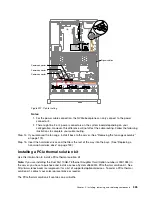
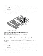
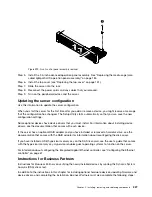
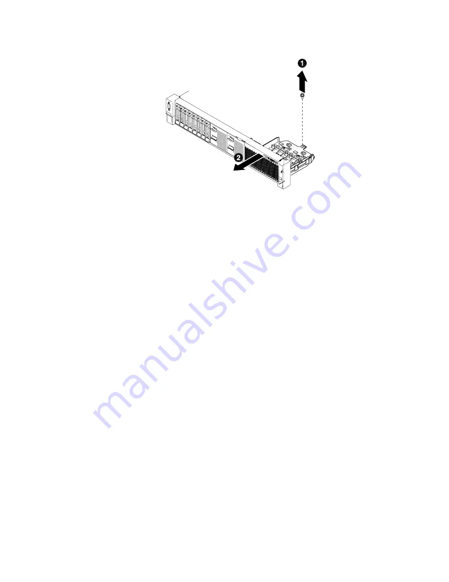
Figure 299. Front control panel assembly removal
Step 5.
Install the 2.5-inch advanced operation panel assembly. See “Replacing the media cage (also
called lightpath LCD operation panel assembly)” on page 184.
Step 6.
Install the top cover (see “Replacing the top cover” on page 151).
Step 7.
Slide the server into the rack.
Step 8.
Reconnect the power cords and any cables that you removed.
Step 9.
Turn on the peripheral devices and the server.
Updating the server configuration
Use this information to update the server configuration.
When you start the server for the first time after you add or remove a device, you might receive a message
that the configuration has changed. The Setup Utility starts automatically so that you can save the new
configuration settings.
Some optional devices have device drivers that you must install. For information about installing device
drivers, see the documentation that comes with each device.
If the server has an optional RAID adapter and you have installed or removed a hard disk drive, see the
documentation that comes with the RAID adapter for information about reconfiguring the disk arrays.
If you have installed a USB hypervisor memory key on the SAS riser-card, see the user's guide that comes
with the hypervisor memory key. Hypervisor enables guest operating systems to function on the server.
For information about configuring the integrated Gigabit Ethernet controller, see “Configuring the Ethernet
controller” on page 61.
Instructions for Business Partners
Instructions for Business Partners on verifying the newly installed devices by running the Dynamic System
Analysis (DSA) stress test.
In addition to the instructions in this chapter for installing optional hardware devices, updating firmware and
device drivers, and completing the installation, Business Partners must also complete the following steps:
Installing, removing, and replacing components
327
Содержание x3650 M5
Страница 1: ...Lenovo System x3650 M5 Installation and Service Guide Machine Type 8871 ...
Страница 47: ...Figure 35 System board switches jumpers and buttons Chapter 1 The System x3650 M5 server 35 ...
Страница 60: ...48 Lenovo System x3650 M5 Installation and Service Guide ...
Страница 80: ...68 Lenovo System x3650 M5 Installation and Service Guide ...
Страница 124: ...112 Lenovo System x3650 M5 Installation and Service Guide ...
Страница 146: ...134 Lenovo System x3650 M5 Installation and Service Guide ...
Страница 1322: ...1310 Lenovo System x3650 M5 Installation and Service Guide ...
Страница 1329: ...People s Republic of China Class A electronic emission statement Taiwan Class A compliance statement Appendix E Notices 1317 ...
Страница 1330: ...Taiwan BSMI RoHS declaration 1318 Lenovo System x3650 M5 Installation and Service Guide ...
Страница 1339: ......
Страница 1340: ......

