• While the device is still in its static-protective package, touch it to an unpainted metal surface on the
outside of the server for at least 2 seconds. This drains static electricity from the package and from
your body.
• Remove the device from its package and install it directly into the server without setting down the device.
If it is necessary to set down the device, put it back into its static-protective package. Do not place the
device on the server cover or on a metal surface.
• Take additional care when handling devices during cold weather. Heating reduces indoor humidity
and increases static electricity.
Installing a 8x 2.5-inch simple-swap HDD ServeRAID assembly kit
Use this information to install a 8x 2.5-inch simple-swap HDD ServeRAID assembly kit.
You can install a Lenovo System x3650 M5 8x 2.5-inch simple-swap HDD ServeRAID assembly kit to support
eight 2.5-inch simple-swap hard disk drives in the server. See http://www.lenovo.com/ serverproven/ for
a list of supported optional devices. To order a 8x 2.5-inch hot-swap HDD assembly kit, contact your
sales representative or reseller.
The 8x 2.5-inch simple-swap HDD ServeRAID assembly kit contains one simple-swap backplate assembly.
To install a 8x 2.5-inch hot-swap HDD assembly kit, complete the following steps:
Step 1.
Read the safety information that begins on “Safety” on page v and “Installation guidelines” on
page 297.
Step 2.
Turn off the server and peripheral devices and disconnect the power cords and all external cables,
if necessary.
Step 3.
Remove the top cover (see “Removing the top cover” on page 149).
Step 4.
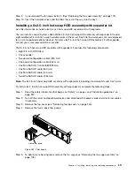
Remove the two 4-drive filler panels.
Step 5.
Pull the hard disk drives or fillers out of the server slightly to disengage them from the backplates.
For more information, (see “Removing a simple-swap hard disk drive” on page 161).
Step 6.
To obtain more working room, remove the fan cage assembly (see “Removing the fan cage
assembly” on page 178).
Step 7.
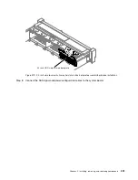
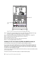
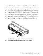
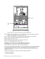
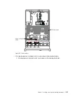
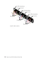
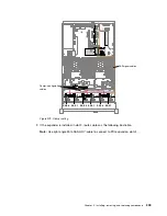
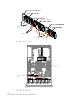
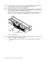
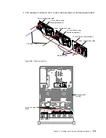
Insert the backplate assembly tabs into slots on the bottom of the cage and push the backplate
assembly forward into the release latch (on top of the backplate assembly cage) until the backplate
assembly is locked in place.
300
Lenovo System x3650 M5 Installation and Service Guide
Содержание x3650 M5
Страница 1: ...Lenovo System x3650 M5 Installation and Service Guide Machine Type 8871 ...
Страница 47: ...Figure 35 System board switches jumpers and buttons Chapter 1 The System x3650 M5 server 35 ...
Страница 60: ...48 Lenovo System x3650 M5 Installation and Service Guide ...
Страница 80: ...68 Lenovo System x3650 M5 Installation and Service Guide ...
Страница 124: ...112 Lenovo System x3650 M5 Installation and Service Guide ...
Страница 146: ...134 Lenovo System x3650 M5 Installation and Service Guide ...
Страница 1322: ...1310 Lenovo System x3650 M5 Installation and Service Guide ...
Страница 1329: ...People s Republic of China Class A electronic emission statement Taiwan Class A compliance statement Appendix E Notices 1317 ...
Страница 1330: ...Taiwan BSMI RoHS declaration 1318 Lenovo System x3650 M5 Installation and Service Guide ...
Страница 1339: ......
Страница 1340: ......

