


For access, do the following:
1. Remove the computer cover. See “Computer cover” on page 56.
2. Remove the front bezel. See “Front bezel” on page 57.
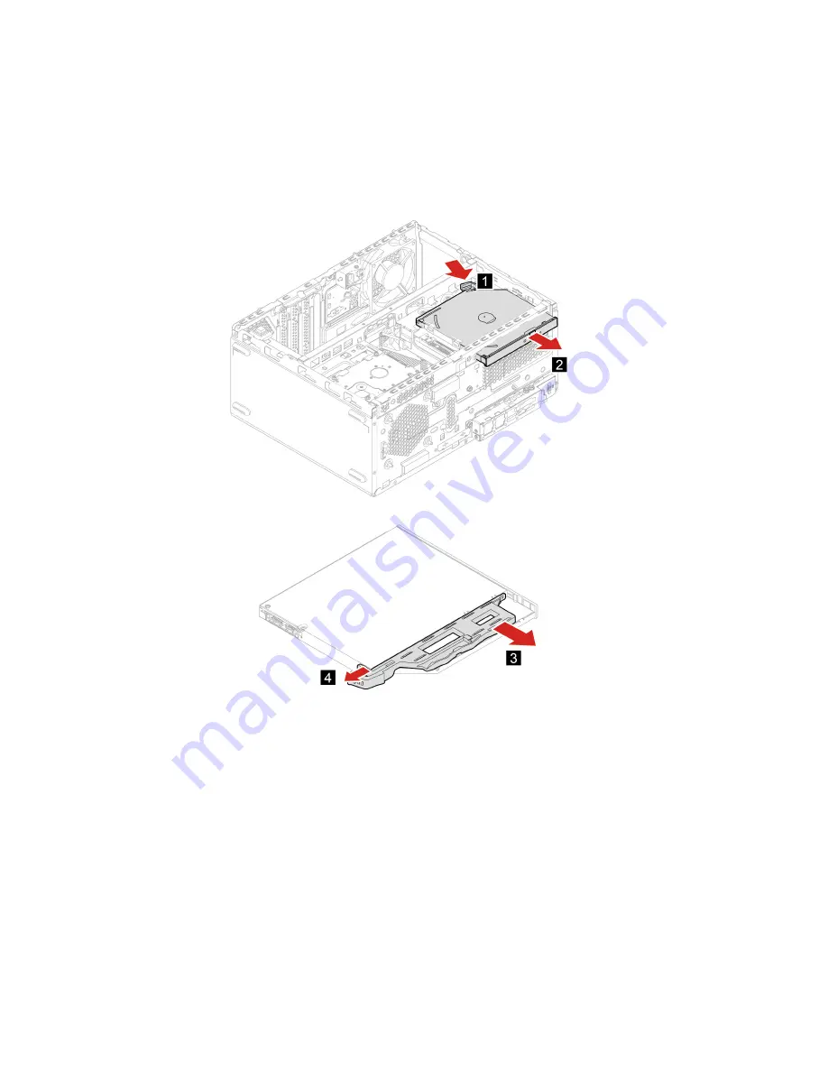
3. Disconnect the signal cable and the power cable from the optical drive.
Removal steps
Drive bay assembly
Prerequisite
Before you start, read
Generic Safety and Compliance Notices
, and print the following instructions.
For access, do the following:
1. Remove the computer cover. See “Computer cover” on page 56.
2. Remove the front bezel. See “Front bezel” on page 57.
58
Lenovo V55t Gen 2 Hardware Maintenance Manual
Содержание V55t Gen 2
Страница 1: ...Lenovo V55t Gen 2 Hardware Maintenance Manual ...
Страница 4: ...System board 79 Notices and trademarks 1 ii Lenovo V55t Gen 2 Hardware Maintenance Manual ...
Страница 6: ......
Страница 13: ...Chapter 1 Important safety information 7 ...
Страница 14: ... 18 kg 37 lb 32 kg 70 5 lb 55 kg 121 2 lb 1 2 8 Lenovo V55t Gen 2 Hardware Maintenance Manual ...
Страница 17: ...Chapter 1 Important safety information 11 ...
Страница 18: ...1 2 12 Lenovo V55t Gen 2 Hardware Maintenance Manual ...
Страница 19: ...Chapter 1 Important safety information 13 ...
Страница 25: ...Chapter 1 Important safety information 19 ...
Страница 29: ...Chapter 1 Important safety information 23 ...
Страница 44: ...38 Lenovo V55t Gen 2 Hardware Maintenance Manual ...
Страница 72: ... Type 2 Type 3 66 Lenovo V55t Gen 2 Hardware Maintenance Manual ...
Страница 82: ...76 Lenovo V55t Gen 2 Hardware Maintenance Manual ...
Страница 89: ......
Страница 90: ......


