42
Lenovo V145 Hardware Maintenance Manual
1080 Fan and heat sink assembly
For access, remove these FRUs in order:
• “1010 Optical drive” on page 32
• “1020 Base cover” on page 33
• “1030 Battery pack” on page 35
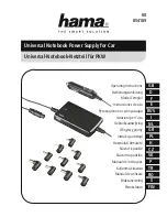
Figure 8. Removal steps of fan and heat sink assembly
Unplug the fan connector in the direction shown by arrow . Remove the
screw . Release the antenna from the cable guides.
2
1
Step Screw (quantity)
Color Torque
M2 × 6 mm, Phillips head, nylok-coated (1)
FAN TO UPPER
Silver
1.85±0.15 kgf*cm
Lift the fan in the direction shown by arrow .
3