Lenovo ThinlPad T14s Gen 1 Скачать руководство пользователя страница 117

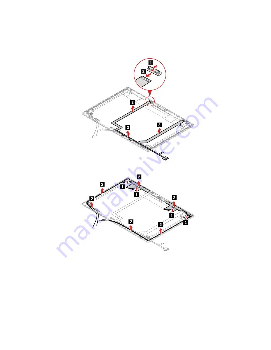
Removal steps of the camera-and-microphone-module cable

Note:

Depending on the type of the camera-and-microphone-module cable, the disconnection steps of the 

cable might be different from the following illustration. For models without camera, skip the disconnection 
steps of the cable.

Removal steps of the antenna kit

Attention:

When you route the cables, ensure that they are not subject to any tension. Tension could cause 

the cables to be damaged by the cable guides, or a wire to be broken.

Chapter 8

.

Removing or replacing a FRU

111

Содержание ThinlPad T14s Gen 1

Страница 1: ...T14s Gen 1 and X13 Gen 1 Hardware Maintenance Manual ...

Страница 2: ...ovo 2020 2021 LIMITED AND RESTRICTED RIGHTS NOTICE If data or software is delivered pursuant to a General Services Administration GSA contract use reproduction or disclosure is subject to restrictions set forth in Contract No GS 35F 05925 ...

Страница 3: ...isk password 31 Supervisor password 32 System management password 32 How to remove the power on password 33 How to remove the hard disk password 33 How to remove the system management password 34 Power management 34 Sleep mode 34 Hibernation mode 35 Symptom to FRU index 35 Numeric error codes 36 Error messages 37 Beep errors 37 No beep symptoms 39 LCD related symptoms 39 Intermittent problems 40 U...

Страница 4: ... cable for ThinkPad T14s Gen 1 only 90 1160 Fingerprint reader bracket and fingerprint reader 92 1170 Smart card reader or dummy smart card reader 92 1180 System board 95 1190 Power card and power card cable 102 1200 LCD unit 103 1210 Keyboard assembly for ThinkPad T14s Gen 1 or Keyboard bezel assembly for ThinkPad X13 Gen 1 105 2010 LCD bezel cover and LCD bezel 105 2020 LCD hinges 106 2030 LCD p...

Страница 5: ...ic tests to troubleshoot problems effectively Depending on the model some hardware configuration and software programs might not be available on the computer Some statements in this manual might not be applicable to the computer Before servicing a ThinkPad product be sure to read all the information under Chapter 1 Safety information on page 1 and Chapter 2 Important service information on page 21...

Страница 6: ...iv T14s Gen 1 and X13 Gen 1 Hardware Maintenance Manual ...

Страница 7: ...icians and the customer s personnel are not in a hazardous position Place removed covers and other parts in a safe place away from all personnel while you are servicing the machine Keep your tool case away from walk areas so that other people will not trip over it Do not wear loose clothing that can be trapped in the moving parts of a machine Ensure that your sleeves are fastened or rolled up abov...

Страница 8: ...ical shock can occur only when there is a complete circuit By observing the above rule you may prevent a current from passing through your body When using testers set the controls correctly and use the approved probe leads and accessories for that tester Stand on suitable rubber mats obtained locally if necessary to insulate you from grounds such as metal floor strips and machine frames Observe th...

Страница 9: ...puter Disconnect the power cord 3 Check the power cord for a A third wire ground connector in good condition Use a meter to measure third wire ground continuity for 0 1 ohm or less between the external ground pin and the frame ground b The power cord should be the authorized type specified for your computer Go to https support lenovo com partslookup c Insulation must not be frayed or worn 4 Check ...

Страница 10: ...ment Note The use of a grounding system to guard against ESD damage is desirable but not necessary Attach the ESD ground clip to any frame ground ground braid or green wire ground When working on a double insulated or battery operated system use an ESD common ground or reference point You can use coax or connector outside shells on these systems Use the round ground prong of the ac plug on ac oper...

Страница 11: ...DANGER DANGER DANGER DANGER DANGER DANGER Chapter 1 Safety information 5 ...

Страница 12: ...DANGER 6 T14s Gen 1 and X13 Gen 1 Hardware Maintenance Manual ...

Страница 13: ...PERIGO Chapter 1 Safety information 7 ...

Страница 14: ...PERIGO PERIGO PERIGO PERIGO 8 T14s Gen 1 and X13 Gen 1 Hardware Maintenance Manual ...

Страница 15: ...PERIGO PERIGO PERIGO DANGER DANGER Chapter 1 Safety information 9 ...

Страница 16: ...DANGER DANGER DANGER DANGER DANGER 10 T14s Gen 1 and X13 Gen 1 Hardware Maintenance Manual ...

Страница 17: ...DANGER VORSICHT VORSICHT VORSICHT VORSICHT Chapter 1 Safety information 11 ...

Страница 18: ...VORSICHT VORSICHT VORSICHT VORSICHT 12 T14s Gen 1 and X13 Gen 1 Hardware Maintenance Manual ...

Страница 19: ...Chapter 1 Safety information 13 ...

Страница 20: ...14 T14s Gen 1 and X13 Gen 1 Hardware Maintenance Manual ...

Страница 21: ...Chapter 1 Safety information 15 ...

Страница 22: ...16 T14s Gen 1 and X13 Gen 1 Hardware Maintenance Manual ...

Страница 23: ...Chapter 1 Safety information 17 ...

Страница 24: ...18 T14s Gen 1 and X13 Gen 1 Hardware Maintenance Manual ...

Страница 25: ...Chapter 1 Safety information 19 ...

Страница 26: ...20 T14s Gen 1 and X13 Gen 1 Hardware Maintenance Manual ...

Страница 27: ...lacing any FRUs listed in this manual After a system board is replaced ensure that the latest UEFI BIOS is loaded to the system board before completing the service action To download software fixes drivers and UEFI BIOS go to https support lenovo com and follow the instructions on the screen Use the following strategy to prevent unnecessary expense for replacing and servicing FRUs If you are instr...

Страница 28: ...pes and how to identify each type Dynamic Configure To Order CTO model This model provides the ability for a customer to configure a Lenovo solution from a Web Site and have this configuration sent to fulfillment where it is built and shipped directly to the customer The machine label and eSupport will load these products as the 4 character MT 4 character model and 2 character country code The mod...

Страница 29: ...2 Type the Machine Type in the corresponding field to get a general FRU list Or type the Serial Number for more detailed FRU information Chapter 2 Important service information 23 ...

Страница 30: ...24 T14s Gen 1 and X13 Gen 1 Hardware Maintenance Manual ...

Страница 31: ... to do with a hardware defect such as cosmic radiation ESD or software errors Consider replacing a FRU only when a problem recurs If you suspect that a FRU is defective clear the error log and run the test again If the error does not recur do not replace the FRU Be careful not to replace a nondefective FRU What to do first When you return a FRU you must include the following information in the par...

Страница 32: ...Pad products The use of non ThinkPad products prototype cards or modified options can lead to false indications of errors and invalid system responses 1 Identify the failing symptoms in as much detail as possible 2 Verify the symptoms Try to re create the failure by running the diagnostic test or by repeating the operation Diagnosing problems Many computer problems can be solved without outside as...

Страница 33: ...mputer If the computer cannot be turned on go to Power system checkout on page 28 and check the power sources If an error code is displayed go to Symptom to FRU index on page 35 for error code descriptions and troubleshooting hints 2 When the logo screen is displayed repeatedly press and release the F10 key The main screen of the UEFI diagnostic program is displayed 3 Follow the instructions on th...

Страница 34: ...ed on go to Power system checkout on page 28 and check the power sources If an error code is displayed go to Symptom to FRU index on page 35 for error code descriptions and troubleshooting hints 2 Insert the disc into the optical drive 3 Restart the computer 4 When the logo screen is displayed repeatedly press and release the F12 key When the Boot Menu window opens release the F12 key 5 Use the ar...

Страница 35: ...em does not support unauthorized batteries or batteries designed for other systems If an unauthorized battery or a battery designed for another systems is installed the system will not charge Attention Lenovo has no responsibility for the performance or safety of unauthorized batteries and provides no warranties for failures or damage arising out of their use Move your pointer to the battery statu...

Страница 36: ...the voltage is correct replace the system board If the voltage is not correct replace the coin cell battery If the coin cell battery discharges quickly after replacement replace the system board 30 T14s Gen 1 and X13 Gen 1 Hardware Maintenance Manual ...

Страница 37: ...s might be needed for a ThinkPad notebook computer the power on password the hard disk password the supervisor password and the system management password If any of these passwords has been set a prompt for it will be displayed on the screen whenever the computer is turned on The computer does not start until the password is entered Note If only a supervisor password is set the password prompt wil...

Страница 38: ...word The system administrator can set the same supervisor password on many ThinkPad notebook computers to make administration easier Attention If the supervisor password has been forgotten and cannot be made available to the service technician there is no service procedure to reset the password The system board must be replaced for a scheduled fee System management password The system management p...

Страница 39: ...r 9 Press F10 to save changes and exit How to remove the hard disk password Attention If User only mode is selected and the user hard disk password has been forgotten and cannot be made available to the service technician neither Lenovo nor Lenovo authorized service technicians provide any services to reset the user hard disk password or to recover data from the solid state drive The solid state d...

Страница 40: ...hen the ThinkPad logo is displayed immediately press F1 3 Type the supervisor password to enter the ThinkPad Setup program 4 Select Security 5 Select Password 6 Select System Management Password 7 Type the current supervisor password in the Enter Current Password field Then leave the Enter New Password field blank and press Enter twice 8 In the Changes have been saved window press Enter 9 Press F1...

Страница 41: ...tion Closing the lid Pressing the power button Also the computer goes into hibernation mode automatically after a period of inactivity specified in power plan settings When the power is turned on the computer returns from hibernation mode and resumes operation The hibernation file in the boot record on the solid state drive is read and system status is restored from the solid state drive Symptom t...

Страница 42: ...e the system board 0189 Invalid RFID configuration information area The EEPROM checksum is not correct Replace the system board 0190 Critical low battery error 1 Charge the battery 2 Replace the battery 0191 System Security Invalid Remote Change requested 1 Run the ThinkPad Setup program and then save current setting by pressing F10 2 Replace the system board 0199 System Security Security password...

Страница 43: ...s 1 Replace the fan 2 Apply thermal grease 3 Replace the system board Thermal sensing error Replace the system board The battery installed is not supported by this system and will not charge Please replace the battery with the correct Lenovo battery for this system Press the ESC key to continue Replace the battery This system does not support batteries that are not genuine Lenovo made or authorize...

Страница 44: ...e Then reconnect all power resources and restart the computer For models without the emergency reset hole press and hold the power button for about seven seconds Then reconnect to all power resources and restart the computer 2 Replace the system board service provider only 0002 Internal bus error Replace the system board service provider only 0281 General embedded controller error Replace the syst...

Страница 45: ...d and press Enter LCD related symptoms Important The TFT LCD for the notebook computer contains many thin film transistors TFTs The presence of a small number of dots that are missing discolored or always lighted is characteristic of TFT LCD technology but excessive pixel problems can cause viewing concerns If the LCD you are servicing has two or less visible defective pixels it should not be cons...

Страница 46: ...with a hardware defect such as cosmic radiation ESD or software errors FRU replacement should be considered only when a problem recurs When analyzing an intermittent problem do the following 1 Run the diagnostic test for the system board in loop mode at least 10 times 2 If no error is detected do not replace any FRUs 3 If any error is detected replace the FRU shown by the FRU code Rerun the test t...

Страница 47: ...If the problem does not recur reconnect the removed devices one at a time until you find the failing FRU 7 If the problem remains replace the following FRUs one at a time do not replace a nondefective FRU a System board b LCD assembly Chapter 4 Related service information 41 ...

Страница 48: ...42 T14s Gen 1 and X13 Gen 1 Hardware Maintenance Manual ...

Страница 49: ...he upper case and lower case When the key indicator is on you can type uppercase letters 3 F1 F12 function keys Invoke the special function printed as an icon on each key or standard function To choose whether to invoke the special function or standard function 1 Go to Control Panel and view by Large icons or Small icons 2 Click Keyboard or Lenovo Keyboard Manager and select the option of your pre...

Страница 50: ...d Darken the computer display Brighten the computer display Manage external displays Enable or disable the built in wireless features Open or collapse the notification center Answer incoming calls on Microsoft Teams Decline incoming calls on Microsoft Teams Invoke the function defined by yourself 1 Open the Start menu and click Lenovo Vantage 2 Click Hardware Settings and then click Input 3 Locate...

Страница 51: ...qual the SysRq key on a conventional external keyboard Fn 4 Put the computer to sleep mode To wake up the computer press Fn or the power button Fn D If your computer supports the PrivacyGuard feature press Fn D to enable or disable this feature Fn Left arrow key Equal the Home key Fn Right arrow key Equal the End key Chapter 5 Special keys 45 ...

Страница 52: ...46 T14s Gen 1 and X13 Gen 1 Hardware Maintenance Manual ...

Страница 53: ...ations Locating computer controls connectors and indicators Front 1 Infrared LED 4 Microphones 2 Camera with IR function 5 Camera 3 ThinkShutter 6 Multi touch screen for selected models Copyright Lenovo 2020 2021 47 ...

Страница 54: ...els AMD models 1 Power button 4 Trackpad 2 Fingerprint reader 5 NFC mark 3 NFC label for selected Intel models 6 TrackPoint pointing device for selected models 48 T14s Gen 1 and X13 Gen 1 Hardware Maintenance Manual ...

Страница 55: ...for Intel models 5 Docking station connector 2 USB C connectors 3 2 Gen 2 for AMD models 6 USB 3 2 connector Gen 1 3 Thunderbolt 3 connector USB C for Intel models 7 HDMI connector 4 Ethernet extension connector Gen 2 8 Audio connector Chapter 6 Locations 49 ...

Страница 56: ...t 3 Security lock slot 2 Always On USB 3 2 connector Gen 1 for selected models Rear 1 System status indicator 2 Nano SIM card and microSD card slot for selected models 50 T14s Gen 1 and X13 Gen 1 Hardware Maintenance Manual ...

Страница 57: ...ook holes 3 Speakers 2 Emergency reset hole Locating FRUs and CRUs This topic introduces the following service parts Major FRUs and CRUs on page 53 LCD FRUs and CRUs on page 59 Miscellaneous parts on page 61 Connector and cable guide on page 61 Chapter 6 Locations 51 ...

Страница 58: ...n screen instructions to find the manual for your product You might be required to return the defective CRU When return is required 1 return instructions a prepaid shipping label and a container will be included with the replacement CRU and 2 you might be charged for the replacement CRU if Lenovo does not receive the defective CRU within thirty 30 days of your receipt of the replacement CRU See yo...

Страница 59: ...Major FRUs and CRUs ThinkPad T14s Gen 1 a b c d Chapter 6 Locations 53 ...

Страница 60: ... 16 Smart card reader cable No No 17 Fingerprint reader bracket No No 18 Fingerprint reader No No 19 Base cover assembly Yes No 20 Trackpad cable for non NFC models No No 21 Trackpad cable for NFC models No No 22 NFC card No No 23 Built in battery No No 24 Speaker assembly No No 25 M 2 2242 solid state drive bracket No Yes 26 M 2 2242 solid state drive No Yes 27 Thermal pad for M 2 2242 solid stat...

Страница 61: ...No for selected models Notes Depending on the computer model your computer might look different from the illustration above The Lenovo factory recovery USB key a is used to restore the Microsoft Windows operating system It might not come with the computer and a user might order it from https pcsupport lenovo com lenovorecovery though additional shipping and handling fees might apply Chapter 6 Loca...

Страница 62: ...ThinkPad X13 Gen 1 a b c d for selected models 56 T14s Gen 1 and X13 Gen 1 Hardware Maintenance Manual ...

Страница 63: ...t reader cable No No 16 Base cover assembly Yes No 17 Fingerprint reader bracket No No 18 Fingerprint reader reader No No 19 Trackpad cable for non NFC models No No 20 Trackpad cable for NFC models No No 21 NFC card No No 22 Built in battery No No 23 M 2 2280 solid state drive No Yes 24 Thermal pad for M 2 2280 solid state drive No No 25 Speaker assembly No No 26 System board No No 27 M 2 2242 sol...

Страница 64: ...odels Notes Depending on the computer model your computer might look different from the illustration above The Lenovo factory recovery USB key a is used to restore the Microsoft Windows operating system It might not come with the computer and a user might order it from https pcsupport lenovo com lenovorecovery though additional shipping and handling fees might apply 58 T14s Gen 1 and X13 Gen 1 Har...

Страница 65: ...e 8 LCD FRUs and CRUs No FRU description Self service CRU Optional service CRU 1 LCD bezel sheet No No 2 LCD bezel No No 3 LCD cable No No 4 Microphone rubber No No 5 Camera and microphone module No No Chapter 6 Locations 59 ...

Страница 66: ...y No No 9 LCD hinges No No 10 Camera and microphone module cable No No 11 LCD cover assembly No No for selected models Note Depending on the computer model the cable might look different from the illustration above For more information about the cable types see 2050 Camera and microphone module cable and antenna kit on page 109 60 T14s Gen 1 and X13 Gen 1 Hardware Maintenance Manual ...

Страница 67: ...lack 4 M2 x L2 2 2 5 black 4 M2 x L2 2 black 10 Spec No No Mechanical miscellaneous kit WWAN card mylar WWAN card absorber Smart card reader mylar Spec No No Label kit Label Spec No No Connector and cable guide This topic provides information to help Lenovo authorized service technicians identify connectors and cables for replacement purpose To view each FRU and the exploded illustration of the co...

Страница 68: ...odule and the other end to this connector 3 Thermal fan connector internal Thermal fan cable The thermal fan comes with the cable Connect the cable to this connector 4 Wireless WAN card slot internal No Insert a wireless WAN card into this slot 5 LCD connector internal LCD cable Connect one end to the LCD panel and the other end to this connector 6 M 2 Solid state drive slot internal No Insert a s...

Страница 69: ...pole plug to this connector 13 Coin cell battery connector internal Coin cell battery cable The coin cell battery comes with cable Connect the cable to this connector 14 Speaker connector internal Speaker cable The speaker comes with the cable Connect the cable to this connector 15 16 Keyboard connectors for ThinkPad T14s Gen 1 internal Keyboard assembly cables The keyboard assembly comes with the...

Страница 70: ...connector For smart card reader and fingerprint reader cable connect one end of the cable to the smart card reader one end to the fingerprint reader and the other end to this connector 20 Always On USB 3 2 connector Gen 1 external Always on USB 3 2 connector Gen 1 cable Connect a USB A compatible device to this connector 21 Nano SIM card and microSD card slot external No Insert a microSD card or N...

Страница 71: ...cable Connect one end to the LCD panel and the other end to this connector 7 M 2 Solid state drive slot internal No Insert a solid state drive into this slot 8 USB C connectors USB 3 2 Gen 2 external No Connect a USB C compatible device to this connector 9 Ethernet extension connector Gen 2 external No Use a ThinkPad Ethernet Extension Adapter Gen 2 to connect your computer to a local area network...

Страница 72: ...d reader and fingerprint reader cable For smart card reader cable connect one end to the smart card reader and the other end to this connector For fingerprint reader cable connect one end to the fingerprint reader and the other end to this connector For smart card reader and fingerprint reader cable connect one end of the cable to the smart card reader one end to the fingerprint reader and the oth...

Страница 73: ...es of the microprocessor and heatsink to eliminate air gaps The hexagonal socket is used to pick up the antenna connectors Screw notices Loose screws can cause a reliability problem In the ThinkPad notebook computer this problem is addressed with special nylon coated screws that have the following characteristics They maintain tight connections They do not easily come loose even with shock or vibr...

Страница 74: ...rs need to remain the same throughout the life of the computer If you replace the system board you must restore the serial number of the system unit to its original value The serial number of the system unit is written on the label attached to the bottom of the computer If you cannot find the serial number of the system unit on the bottom of the computer try the following method to get the number ...

Страница 75: ...d does not have a UUID Note For Intel models before you perform the operation ensure that the UEFI Legacy setting within the Startup menu in the ThinkPad Setup program is set to UEFI Only 1 Connect a USB memory key to the computer 2 Go to https www lenovo com maintenanceutilities and follow the instructions on the screen to create a Maintenance Key Note Only an authorized Lenovo service technician...

Страница 76: ...the same as the machine type of the machine that had the ECA applied to it 1 Insert the latest version of LENOVO ThinkPad Hardware Maintenance Diskette or Maintenance Key and then restart the computer 2 From the main menu select 6 Set ECA Information 3 To write the ECA information select 1 Write ECA rework number from EEPROM and follow the instructions on the screen To write the box build date sel...

Страница 77: ...he correct screws as shown in the replacement procedures DANGER Before removing any FRU turn off the computer unplug all power cords from electrical outlets disable the built in battery and then disconnect any interconnecting cables Attention After replacing a FRU do not turn on the computer until you have made sure that all screws springs and other small parts are in place and none are loose insi...

Страница 78: ...ing the nano SIM card and microSD card tray Note If the computer you are servicing has a nano SIM card or microSD card installed remove the card with the tray together 1010 Keyboard for ThinkPad X13 Gen 1 only Removal steps of the keyboard Notes You might be instructed to slide the keyboard frame forward or backward in some of the following steps In this case ensure that you do not press or hold t...

Страница 79: ...a b c d Chapter 8 Removing or replacing a FRU 73 ...

Страница 80: ...ng Configure the keyboard language in UEFI BIOS 1 Enter the UEFI BIOS menu 2 Click Config Keyboard Mouse Keyboard Layout and then select the keyboard language 74 T14s Gen 1 and X13 Gen 1 Hardware Maintenance Manual ...

Страница 81: ...1020 Base cover assembly Removal steps Chapter 8 Removing or replacing a FRU 75 ...

Страница 82: ...ace the base cover assembly For the labels that are not shipped with the new base cover assembly peel them from the old base cover assembly and adhere them to the new one ThinkPad T14s Gen 1 1 SVT label 2 Asset tag 3 COA label 4 Genuine Microsoft label Windows 10 5 S N label 6 Country label 7 IMEI label 8 CMIIT label ThinkPad X13 Gen 1 1 IMEI label 2 Genuine Microsoft label Windows 10 3 S N label ...

Страница 83: ...want to keep Do not apply pressure to the M 2 solid state drive Do not touch the contact edge or circuit board of the M 2 solid state drive Otherwise the M 2 solid state drive might get damaged Do not make the M 2 solid state drive subject to physical shocks or vibration Put the M 2 solid state drive on a soft material such as cloth to absorb physical shocks If your computer is installed with a hy...

Страница 84: ...ad Type one Step Screw quantity Color Torque 1 M2 2 2 mm flat head nylon coated 2 Black 0 181 Nm 1 85 kgf cm Type two Step Screw quantity Color Torque 1 M2 2 2 mm flat head nylon coated 1 Black 0 181 Nm 1 85 kgf cm 78 T14s Gen 1 and X13 Gen 1 Hardware Maintenance Manual ...

Страница 85: ... Color Torque 2 M2 2 2 mm flat head nylon coated 1 Black 0 181 Nm 1 85 kgf cm When installing Plug the orange cable into the main connector and the blue cable into the auxiliary connector on the card 1050 Wireless LAN card for AMD models For access remove this FRU 1020 Base cover assembly on page 75 Chapter 8 Removing or replacing a FRU 79 ...

Страница 86: ...ng out of their use The Lenovo Solution Center program provides an automatic battery diagnostic test that determines if the battery is defective A battery FRU should not be replaced unless this diagnostic test shows that the battery is defective The only exception to this is if the battery is physically damaged or a customer is reporting a possible safety issue If the Lenovo Solution Center progra...

Страница 87: ...Removal steps ThinkPad T14s Gen 1 Step Screw quantity Color Torque 2 M2 4 5 mm flat head nylon coated 5 Black 0 181 Nm 1 85 kgf cm Chapter 8 Removing or replacing a FRU 81 ...

Страница 88: ... When installing Ensure that the connector is attached firmly Ensure that the base cover assembly is secured in place Otherwise the battery connection may fail 1070 Docking station connector bracket For access remove this FRU 1020 Base cover assembly on page 75 82 T14s Gen 1 and X13 Gen 1 Hardware Maintenance Manual ...

Страница 89: ...ure that the two latches on the bracket are secured in place 1080 Thermal fan assembly For access remove this FRU 1020 Base cover assembly on page 75 Removal steps 2a 2d 2b 2c When installing Ensure that the connector is attached firmly Do not press the top of the fan cover and the fan hub Chapter 8 Removing or replacing a FRU 83 ...

Страница 90: ... Either too much or too less application of grease can cause a thermal problem due to imperfect contact with a component 1090 USB card cable and USB card For access remove these FRUs 1020 Base cover assembly on page 75 1080 Thermal fan assembly on page 83 Removal steps of the USB card and USB card cable 84 T14s Gen 1 and X13 Gen 1 Hardware Maintenance Manual ...

Страница 91: ...85 kgf cm 1100 Coin cell battery DANGER Use only the authorized battery specified for the computer Any other battery could ignite or explode For access remove these FRUs in order 1020 Base cover assembly on page 75 1060 Built in battery on page 80 Chapter 8 Removing or replacing a FRU 85 ...

Страница 92: ...ctor is attached firmly 1110 Trackpad cable For access remove these FRUs in order 1020 Base cover assembly on page 75 1060 Built in battery on page 80 Removal steps of trackpad cable for NFC models 86 T14s Gen 1 and X13 Gen 1 Hardware Maintenance Manual ...

Страница 93: ...ackpad cable on page 86 Removal steps of trackpad Table 12 Screw specification ThinkPad T14s Gen 1 Step Screw quantity Color Torque 1 M2 2 mm flat head nylon coated 4 Black 0 181 Nm 1 85 kgf cm Table 13 Screw specification ThinkPad X13 Gen 1 Step Screw quantity Color Torque 1 M2 1 8 mm flat head nylon coated 4 Silver 0 181 Nm 1 85 kgf cm When installing Ensure that the connectors are attached firm...

Страница 94: ... on page 75 1060 Built in battery on page 80 Removal steps 1140 Speaker assembly For access remove these FRUs in order 1020 Base cover assembly on page 75 1060 Built in battery on page 80 Removal steps ThinkPad T14s Gen 1 88 T14s Gen 1 and X13 Gen 1 Hardware Maintenance Manual ...

Страница 95: ... 2 M2 x 2 2 2 4 mm flat head nylon coated 4 Black 0 181 Nm 1 85 kgf cm ThinkPad X13 Gen 1 Step Screw quantity Color Torque 2 M2 x 2 2 2 5 mm flat head nylon coated 4 Black 0 181 Nm 1 85 kgf cm Chapter 8 Removing or replacing a FRU 89 ...

Страница 96: ...eader cable fingerprint reader cable and smart card reader cable for ThinkPad T14s Gen 1 only For access remove these FRUs in order 1020 Base cover assembly on page 75 1060 Built in battery on page 80 ThinkPad T14s Gen 1 Removal steps of the fingerprint reader and smart card reader cable 90 T14s Gen 1 and X13 Gen 1 Hardware Maintenance Manual ...

Страница 97: ...r cable Removal steps of the smart card reader cable ThinkPad X13 Gen 1 Removal steps of the fingerprint reader and smart card reader cable Note For models without fingerprint reader skip step 3 and 4 Chapter 8 Removing or replacing a FRU 91 ...

Страница 98: ... card reader cable for ThinkPad T14s Gen 1 only on page 90 Removal steps Step Screw quantity Color Torque 1 M2 2 2 mm flat head nylon coated 1 Black 0 181 Nm 1 85 kgf cm 1170 Smart card reader or dummy smart card reader For access remove these FRUs in order 1020 Base cover assembly on page 75 1060 Built in battery on page 80 1140 Speaker assembly on page 88 1150 Fingerprint reader and smart card r...

Страница 99: ...w quantity Color Torque 1 M2 2 2 mm flat head nylon coated 3 Black 0 181 Nm 1 85 kgf cm Removal steps of the dummy smart card reader Step Screw quantity Color Torque 1 M2 2 2 mm flat head nylon coated 2 Black 0 181 Nm 1 85 kgf cm Chapter 8 Removing or replacing a FRU 93 ...

Страница 100: ...ty Color Torque 1 M2 2 2 mm flat head nylon coated 3 Black 0 181 Nm 1 85 kgf cm Removal steps of the dummy smart card reader Step Screw quantity Color Torque 1 M2 2 2 mm flat head nylon coated 3 Black 0 181 Nm 1 85 kgf cm 94 T14s Gen 1 and X13 Gen 1 Hardware Maintenance Manual ...

Страница 101: ...e surface For access remove these FRUs in order 1010 Keyboard for ThinkPad X13 Gen 1 only on page 72 1020 Base cover assembly on page 75 1030 M 2 solid state drive bracket and thermal pad on page 77 1040 Wireless WAN card for selected models on page 79 1050 Wireless LAN card for AMD models on page 79 1060 Built in battery on page 80 1070 Docking station connector bracket on page 82 1080 Thermal fa...

Страница 102: ...1 Step Screw quantity Color Torque 20 M2 3 mm flat head nylon coated 4 Silver 0 181 Nm 1 85 kgf cm 21 M2 2 2 mm flat head nylon coated 2 Black 0 181 Nm 1 85 kgf cm 96 T14s Gen 1 and X13 Gen 1 Hardware Maintenance Manual ...

Страница 103: ... Configure the keyboard language in UEFI BIOS 1 Enter the UEFI BIOS menu 2 Click Config Keyboard Mouse Keyboard Layout and then select the keyboard language ThinkPad X13 Gen 1 Chapter 8 Removing or replacing a FRU 97 ...

Страница 104: ...ick Config Keyboard Mouse Keyboard Layout and then select the keyboard language AMD models This computer shares a common system board with another computer After replacing the system board you will be prompted to input a brand name to correctly identify the machine type The following table contains the brand name required to complete this step Note Input the exact brand name as shown in this table...

Страница 105: ...te If you want to install a system board with the Linux operating system you need to configure Sleep State in UEFI BIOS to ensure that the system works correctly 1 Enter the UEFI BIOS menu 2 Select Config Power using the arrow keys 3 Locate the Sleep State section and then select Linux ThinkPad T14s Gen 1 Chapter 8 Removing or replacing a FRU 99 ...

Страница 106: ... BIOS menu 2 Click Config Keyboard Mouse Keyboard Layout and then select the keyboard language Note If you want to install a system board with the Linux operating system you need to configure Sleep State in UEFI BIOS to ensure that the system works correctly 1 Enter the UEFI BIOS menu 2 Select Config Power using the arrow keys 3 Locate the Sleep State section and then select Linux 100 T14s Gen 1 a...

Страница 107: ...13 Gen 1 Step Screw quantity Color Torque 16 M2 3 mm flat head nylon coated 4 Silver 0 181 Nm 1 85 kgf cm 17 M2 2 2 mm flat head nylon coated 2 Black 0 181 Nm 1 85 kgf cm Chapter 8 Removing or replacing a FRU 101 ...

Страница 108: ... card and power card cable Removal steps of power card and power card cable For access remove this FRU 1010 Keyboard for ThinkPad X13 Gen 1 only on page 72 1020 Base cover assembly on page 75 1030 M 2 solid state drive bracket and thermal pad on page 77 1040 Wireless WAN card for selected models on page 79 1050 Wireless LAN card for AMD models on page 79 1060 Built in battery on page 80 1070 Docki...

Страница 109: ... 3 mm flat head nylon coated 1 Silver 0 181 Nm 1 85 kgf cm When installing Ensure that the connector is attached firmly 1200 LCD unit For access remove this FRU 1020 Base cover assembly on page 75 Chapter 8 Removing or replacing a FRU 103 ...

Страница 110: ... head nylon coated 6 Silver 0 294 Nm 3 0 kgf cm Table 15 Screw specification ThinkPad X13 Gen 1 Step Screw quantity Color Torque 2 M 2 5 4 5 mm flat head nylon coated 6 Silver 0 294 Nm 3 0 kgf cm When installing Ensure that the connectors are attached firmly 104 T14s Gen 1 and X13 Gen 1 Hardware Maintenance Manual ...

Страница 111: ...nnector bracket on page 82 1080 Thermal fan assembly on page 83 1090 USB card cable and USB card on page 84 1100 Coin cell battery on page 85 1110 Trackpad cable on page 86 1120 Trackpad on page 87 1130 NFC card on page 88 1140 Speaker assembly on page 88 1150 Fingerprint reader and smart card reader cable fingerprint reader cable and smart card reader cable for ThinkPad T14s Gen 1 only on page 90...

Страница 112: ...moved it cannot be used anymore A new LCD bezel sheet is required for replacement 2020 LCD hinges For access remove these FRUs in order 1020 Base cover assembly on page 75 1200 LCD unit on page 103 2010 LCD bezel cover and LCD bezel on page 105 Removal steps 106 T14s Gen 1 and X13 Gen 1 Hardware Maintenance Manual ...

Страница 113: ...l cover and LCD bezel on page 105 2020 LCD hinges on page 106 Removal steps Attention The LCD panel might be fixed to the LCD cover assembly by tapes remove the LCD panel carefully Inappropriate handling might cause damage to the LCD panel When installing Ensure that the connector is attached firmly Notes For LCD panel with the factory color calibration feature do the following to install new colo...

Страница 114: ...remove these FRUs in order 1020 Base cover assembly on page 75 1200 LCD unit on page 103 2010 LCD bezel cover and LCD bezel on page 105 2020 LCD hinges on page 106 2030 LCD panel and LCD cable on page 107 Note Depending on the type of the camera and microphone module cable the disconnection steps of the cable might be different from the following illustrations For more information see 2050 Camera ...

Страница 115: ...over assembly on page 75 1200 LCD unit on page 103 2010 LCD bezel cover and LCD bezel on page 105 2020 LCD hinges on page 106 2030 LCD panel and LCD cable on page 107 Camera and microphone module cable types Depending on the computer model the camera and microphone module cable might be one of the following types Chapter 8 Removing or replacing a FRU 109 ...

Страница 116: ...em status indicator For models with system status indicator only For models with IR camera microphone and system status indicator For models with conventional camera microphone and system status indicator For models with microphone and system status indicator For models with system status indicator only 110 T14s Gen 1 and X13 Gen 1 Hardware Maintenance Manual ...

Страница 117: ...ight be different from the following illustration For models without camera skip the disconnection steps of the cable Removal steps of the antenna kit Attention When you route the cables ensure that they are not subject to any tension Tension could cause the cables to be damaged by the cable guides or a wire to be broken Chapter 8 Removing or replacing a FRU 111 ...

Страница 118: ...r access remove these FRUs in order 1020 Base cover assembly on page 75 1200 LCD unit on page 103 2010 LCD bezel cover and LCD bezel on page 105 2020 LCD hinges on page 106 2030 LCD panel and LCD cable on page 107 2040 Camera and microphone module and aluminum foil for ThinkPad T14s Gen 1 only on page 108 2050 Camera and microphone module cable and antenna kit on page 109 112 T14s Gen 1 and X13 Ge...

Страница 119: ...ication Lenovo may make improvements and or changes in the product s and or the program s described in this publication at any time without notice The products described in this document are not intended for use in implantation or other life support applications where malfunction may result in injury or death to persons The information contained in this document does not affect or change Lenovo pr...

Страница 120: ...crosoft and Windows are trademarks of the Microsoft group of companies The terms HDMI and HDMI High Definition Multimedia Interface are trademarks or registered trademarks of HDMI Licensing LLC in the United States and other countries USB C is a trademark of USB Implementers Forum All other trademarks are the property of their respective owners 2021 Lenovo 114 T14s Gen 1 and X13 Gen 1 Hardware Mai...

Страница 121: ...able Unit CTO Configure To Order EAIA Enhanced Asset Information Area EEPROM Electrically Erasable Programmable Read Only Memory EFI Extensible Firmware Interface ESD Electrostatic discharge FRU Field Replaceable Unit GAV General Announce Variant IC Integrated circuits LCD Liquid Crystal Display MTM Machine type and model POST Power on self test RFID Radio frequency identification SVP Supervisor p...

Страница 122: ...116 T14s Gen 1 and X13 Gen 1 Hardware Maintenance Manual ...

Страница 123: ......

Страница 124: ...Part Number SP40T79957_01 Printed in China 1P P N SP40T79957_01 1PSP40T79957_01 ...

Отзывы: