background image

Controller and expansion modules

43

Controller and expansion modules

This section describes the IOMs used in Lenovo ThinkSystem DS Series storage enclosures. They are 

mechanically and electrically compliant to the latest SBB v2.1 specification.
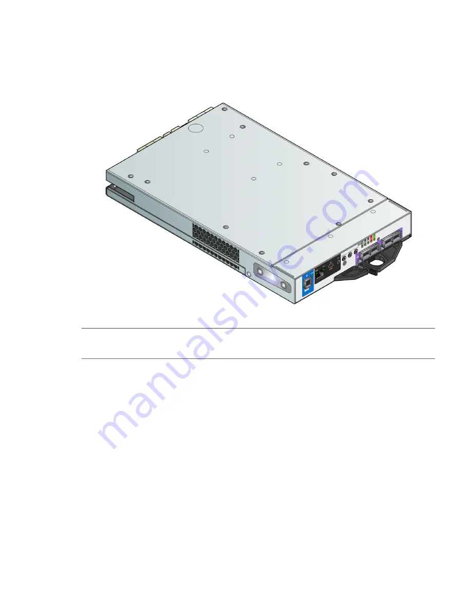
The isometric rear orientation in 

Figure 36

 shows a frontal face plate view of a 4-port FC/iSCSI controller module 

aligned for use in the top controller module slot located on the 2U enclosure rear panel.

Figure 36 Controller module – isometric rear orientation

NOTE:

Given that the 5U84 is configured as an EBOD, it does not support controller modules. Rather, it 

supports the expansion module used by DS EXP enclosures. See 

Figure 43 (page 52)

 and 

Figure 77 (page 115)

.

Each controller module maintains VPD (Vital Product Data) in EEPROM devices, and are interconnected by 

SBB-defined I

2

C buses on the midplane. In this way, the SBB modules can discover the type and capabilities of the 

partner SBB module(s), and vice versa, within the enclosure. An enclosure system alarm occurs when incompatible 

configurations are detected.

12Gb/s controller module LEDs

The diagrams with tables that immediately follow provide descriptions for the different controller modules that can 

be installed into the rear panel of a DS Series and DS EXP/D3284 controller enclosure. Showing controller 

modules separately from the enclosure enables improved clarity in identifying the component items called out in 

the diagrams and described in the companion tables within the figure/table ensembles. In each IOM diagram, the 

controller module is oriented for insertion into the top IOM slot (A). When oriented for use in the bottom IOM slot 

(B), the IOM labels appear upside down.

Содержание ThinkSystem D3284

Страница 1: ...ThinkSystem DS Series and DS EXP D3284 Hardware Installation and Maintenance Guide Machine Type 4619 4617 4599 4588 6413 ...

Страница 2: ...S SERIES FLEX SYSTEM NEXTSCALE SYSTEM SYSTEMX and THINKSYSTEM are trademarks of Lenovo All other trademarks are the property of their respective owners 2019 Lenovo This information could include technical inaccuracies or typographical errors Changes are periodically made to the information herein these changes will be incorporated in new editions of the publication Lenovo may make improvements and...

Страница 3: ...losure variants 25 2U12 25 2U24 25 D3284 25 2U enclosure core product 26 2U enclosure front panel 26 2U enclosure rear panel 27 2U enclosure chassis 30 5U enclosure core product 32 5U enclosure front panel 33 5U enclosure rear panel 34 5U enclosure chassis 35 5U enclosure drawers 35 Operator s Ops panel 36 2U enclosure Ops panel 36 5U enclosure Ops panel 37 Power cooling module 2U enclosures 39 58...

Страница 4: ...1 Testing enclosure connections 71 Grounding checks 72 Host system requirements 72 Cabling considerations 72 Connecting the enclosure to hosts 72 CNC technology 73 HD mini SAS 75 Host connection 76 Fibre Channel host connection 76 10GbE iSCSI host connection 76 1Gb iSCSI host connection 76 HD mini SAS host connection 76 Connecting a management host on the network 79 Updating firmware 79 New user s...

Страница 5: ...sensors 102 Troubleshooting 2U enclosures 103 PCM Faults 103 Thermal monitoring and control 104 Thermal alarm 104 Troubleshooting 5U enclosures 105 Thermal considerations 105 USB CLI port connection 105 Fault isolation methodology 105 Basic steps 107 Options available for performing basic steps 107 Performing basic steps 108 If the enclosure does not initialize 109 Correcting enclosure IDs 109 Hos...

Страница 6: ...nfiguring partner firmware update 128 Verifying component failure 128 Stopping I O 128 Shutting down a controller module 129 Removing an IOM 130 Installing an IOM 131 Verifying component operation 132 CRU replacement for 5U chassis 133 Accessing drawers 133 Opening a drawer 133 Closing a drawer 134 Replacing a DDIC 134 Removing a DDIC 134 Installing a DDIC 137 Populating drawers 137 Preparation 13...

Страница 7: ...Taiwan BSMI RoHS declaration 152 C USB device connection 153 Rear panel USB ports 153 USB CLI port 153 Emulated serial port 153 Supported host applications 154 Command line interface 154 Device driver special operation mode 154 Microsoft Windows 154 Using the CLI port and cable known issues on Windows 155 Problem 155 Workaround 155 D SFP option for CNC ports 156 Locate the SFP transceivers 156 Ins...

Страница 8: ...84 29 22 Power cooling module PCM detail 30 23 2U12 enclosure chassis isometric front orientation 31 24 2U24 enclosure chassis isometric front orientation 31 25 5U84 enclosure system front panel components 33 26 5U84 enclosure system plan view of drawer accessed from front panel 33 27 5U84 expansion enclosure rear panel components 34 28 Power supply unit PSU detail 34 29 Fan cooling module FCM det...

Страница 9: ...AN fabric 79 68 Connecting a USB cable to the CLI port 82 69 Connecting two DS6200 DS4200 storage systems for replication multiple servers one switch one location 89 70 Connecting two DS2200 storage systems for replication multiple servers one switch one location 89 71 Connecting two DS6200 DS4200 storage systems for replication multiple servers switches one location 90 72 Connecting two DS2200 st...

Страница 10: ...moving an FCM 2 of 2 141 102 IOM latch operation detail 143 103 Removing an IOM 1 of 2 143 104 Removing an IOM 2 of 2 144 105 USB device connection CLI port 153 106 Install a qualified SFP option into an DS4200 or DS6200 FC iSCSI controller module 156 107 Install a qualified SFP option into an DS2200 FC iSCSI controller module 157 ...

Страница 11: ... 100 20 Drawer LED descriptions 101 21 2U alarm conditions 103 22 5U alarm conditions 105 23 DS6200 enclosure models 111 24 DS4200 enclosure models 111 25 DS2200 enclosure models 111 26 DS4200 DS2200 DS EXP product components for 2U 12 drive chassis 112 27 DS6200 DS4200 DS2200 DS EXP product components for 2U 24 drive chassis 113 28 D3284 product components for 5U 84 drive chassis 114 29 2U enclos...

Страница 12: ...ion characteristics for controller and optional expansion enclosures DS6200 DS4200 DS2200 and optional DS EXP products use the same 2U24 and 2U12 chassis form factors DS6200 is only available in the 2U24 chassis DS6200 and DS4200 provide four host ports per controller I O module SBB RAID canister DS2200 provides two host ports per controller I O module DS6200 DS4200 DS2200 models are configured wi...

Страница 13: ...ost interface protocol The 2 port DS2200 models do not support SFPs for multiple host interface protocols in combination You must select a common host interface protocol and SFP for use in all CNC ports within the controller enclosure See CNC technology page 73 Figure 17 page 28 and Figure 18 page 28 for more information TIP See the CLI Reference Guide for information about configuring CNC ports w...

Страница 14: ...rt licenses and product documentation Lenovo Read Me First1 Overview of product shipkit contents and setup tasks Lenovo ThinkSystem DS Series and DS EXP D3284 Getting Started1 Using the web interface to configure and manage the product Lenovo ThinkSystem DS Series and DS EXP D3284 Storage Manager Guide2 Using the command line interface CLI to configure and manage the product Lenovo ThinkSystem DS ...

Страница 15: ...Cross reference links Black underlined text Email addresses Colored underlined text Website addresses Bold text Keys that are pressed Text entered into a GUI element such as a box GUI elements that are clicked or selected such as menu and list items buttons and check boxes Italic text Text emphasis Monospace text File and directory names System output Code Commands their arguments and argument val...

Страница 16: ...enclosure weighs 46 kg 101 lb Use appropriate lifting methods Before lifting the enclosure Unplug all cables and label them for reconnection Remove DDICs from drawers and verify the drawers are closed firmly and locked See also Figure 25 page 33 Use a minimum of three people to lift the enclosure using the lifting straps provided Avoid lifting the enclosure using the handles on any of the CRUs bec...

Страница 17: ...an one 5U84 enclosure do not open more than one drawer per rack at a time Observe the hot surface label affixed to the drawer Operating temperatures inside the enclosure drawers can reach 60ºC Take care when opening drawers and removing DDICs Due to product acoustics ear protection should be worn during prolonged exposure to the product in operation Observe the drawer caution label Open drawers mu...

Страница 18: ...ting the total weight of the installed enclosures The design should incorporate stabilizing features suitable to prevent the rack from tipping or being pushed over during installation or in normal use When loading a rack with enclosures fill the rack from the bottom up and empty the rack from the top down Always remove all power supply modules to minimize weight before loading the enclosure into t...

Страница 19: ...ge current of 1 0mA The design of the electrical distribution system must take into consideration the total earth leakage current from all power supply modules in all enclosures The rack will require labeling with High Leakage Current Earth connection essential before connecting supply The rack when configured with the enclosures must meet the safety requirements of UL 60950 1 and IEC 60950 1 ...

Страница 20: ...the controller module rather than directly to the disks Later when the storage system is either idle or aging and continuing to receive new I O data the controller writes the data to the disks Read ahead caching The controller detects sequential data access reads ahead into the next sequence of data based upon settings and stores the data in the read ahead cache Then if the next read access is for...

Страница 21: ...Supercapacitor pack 21 data in the write cache to the CompactFlash in the event of a power failure Unwritten data in CompactFlash memory is automatically committed to disk media when power is restored ...

Страница 22: ... Status LED blinks at a rate of 1 10 second on and 9 10 second off See also Cache Status LED details page 50 Please refer to Enclosure variants page 25 for details about various enclosure options Figure 5 2U12 enclosure system isometric front orientation Figure 6 2U12 enclosure system isometric rear orientation ...

Страница 23: ...uipped with dual controllers 4 port FC iSCSI model shown NOTE Please refer to Enclosure variants page 25 for details about various enclosure options Figure 7 2U24 enclosure system isometric front orientation Figure 8 2U24 enclosure system isometric rear orientation ...

Страница 24: ... enclosure above is equipped with dual controllers 4 port SAS model shown Figure 9 5U84 enclosure system isometric front and rear orientations Isometric front view orientation Isometric rear view orientation EBOD is equipped with dual IOMS ...

Страница 25: ...atible modules of the same type both AC 2 Supported controller module IOMs include 4 port or 2 port FC iSCSI and 4 port or 2 port HD mini SAS Supported expansion module IOMs are used in expansion enclosures for adding storage D3284 84 x LFF or SFF disk drives not interchangeable held in two 42 slot vertically stacked drawers 1 The D3284 is not supported by DS2200 The D3284 is compatible with DS620...

Страница 26: ...plug in modules A typical enclosure system as supplied includes the following An enclosure chassis which includes the midplane PCB and an integral operator s Ops panel that is mounted on the left ear flange at the front of the enclosure Two 580W 100 240V AC power cooling modules See also Figure 33 page 39 Two IOMs 2 x SBB compliant interface slots Up to 24 disk drive modules Where appropriate the ...

Страница 27: ...ODs use 2 port controller modules The DS Series RBODs support the DS EXP EBODs for optionally adding storage The DS6200 and DS4200 RBODs also support the D3284 EBOD Figure 12 2U controller enclosure rear panel components 4 port FC iSCSI Figure 13 2U controller enclosure rear panel components 2 port FC iSCSI Figure 14 2U controller enclosure rear panel components 4 port SAS Figure 15 2U controller ...

Страница 28: ...an be configured with 8 16Gb s FC SFPs 10GbE iSCSI SFPs or Gb s RJ 45 SFPs See Install an SFP transceiver page 156 for installing qualified SFP options in CNC ports Figure 17 4 port FC iSCSI controller module detail DS6200 DS4200 Figure 18 2 port FC iSCSI controller module detail DS2200 only Figure 19 and Figure 20 show SAS host interface ports that ship configured with 12Gb s HD mini SAS SFF 8644...

Страница 29: ...f the expansion canister shows the module aligned for use in A This orientation also applies to canister insertion into either IOM slot located on the D3284 enclosure rear panel Figure 21 Expansion module detail DS EXP and D3284 IMPORTANT RBOD EBOD configurations When the expansion module shown above Figure 21 is used with DS Series controller modules for adding storage its middle HD mini SAS expa...

Страница 30: ... uses two EIA units of rack space 3 5 for a 2U enclosure The midplane PCB can support either 12 or 24 disk drive connections There are either 12 or 24 drive slots at the front of the enclosure in horizontal 12 or vertical 24 orientation as defined by the enclosure variant See also Figure 10 and Figure 11 page 26 Each drive slot holds a plug in drive carrier module that can hold these drive types d...

Страница 31: ...2U12 enclosure chassis isometric front orientation Figure 24 2U24 enclosure chassis isometric front orientation NOTE Either 2U chassis can be configured as a controller enclosure or as an optional expansion enclosure for adding storage ...

Страница 32: ...ated within two drawers 42 DDICs per drawer 14 DDICs per row TIP The 5U84 does not ship with DDICs installed DDICs ship in a separate container and must be installed into the enclosure drawers during product installation and setup See the Installation checklist table on page 59 A rail kit for rack mounting NOTE 5U84 enclosure configuration characteristics D3284 is the high density 5U84 expansion e...

Страница 33: ...iew is scaled and rotated 90º about the vertical axis to better fit the page and the conceptual graphics are simplified for clarity 0 42 1 43 2 44 3 45 4 46 5 47 6 48 7 49 8 50 9 51 10 52 11 53 12 54 13 55 14 56 15 57 16 58 17 59 18 60 19 61 20 62 21 63 22 64 23 65 24 66 25 67 26 68 27 69 28 70 29 71 30 72 31 73 32 74 33 75 34 76 35 77 36 78 37 79 38 80 39 81 40 82 41 83 Drawer front panel Into sl...

Страница 34: ...dicate slot sequencing for modules used in 5U enclosures PSU FCM and IOM modules are available as CRUs These EBODs use the same 3 port expansion modules used by 2U enclosures for optionally adding storage Figure 27 5U84 expansion enclosure rear panel components 5U rear panel components Expansion module The 5U84 expansion enclosure uses the same IOM used by 2U12 and 2U24 enclosures See Expansion mo...

Страница 35: ...hassis form factors used for configuring EBODs 5U84 chassis configured with up to 84 LFF disks in DDICs see Figure 26 page 33 5U84 chassis configured with SFF disks in SFF disks in 2 5 to 3 5 hybrid driver carrier adapter 5U84 empty chassis with midplane module runner system and drawers The chassis has a 19 inch rack mounting that enables it be installed onto standard 19 inch racks and uses five E...

Страница 36: ...nti tamper locks clockwise using a screwdriver with a Torx T20 bit The anti tamper locks are symmetrically placed on the left hand and right hand sides of the drawer bezel Drawer status and activity LEDs can be monitored via two Drawer LEDs panels located next to the two drawer pull pockets located on the left hand and right hand side of each drawer Figure 30 Drawer bezel details NOTE Figure 30 sh...

Страница 37: ... be used to provide feedback to the user Its primary function is to display an enclosure unit identification number to assist users in setting and maintaining multiple enclosure systems Thermal sensor The thermal sensor is located on the outside of the enclosure and it sends input to the enclosure about its external operating ambient temperature 5U enclosure Ops panel The enclosure front panel has...

Страница 38: ...when experiencing a system hardware fault It may be associated with a Fault LED on a PSU FCM IOM DDIC or Drawer that helps the user to identify which component is causing the fault Logical Status LED amber LED indicates a change of status or fault from something other than the enclosure management system This may be initiated from the controller module or an external HBA The indication is typicall...

Страница 39: ...l frontal view of a PCM panel located on the enclosure rear panel see Figure 22 page 30 Multiple PCMs The 2U storage system includes two PCMs which provide redundant power control for the system so that if one PCM fails the other maintains the power supply and enclosure operation is not affected while you replace the faulty module 580W Power Cooling Module LED descriptions see inset illustration d...

Страница 40: ...provides sufficient capacity to ensure that maximum temperatures are not exceeded IMPORTANT The environment in which the enclosure operates must be dust free to ensure adequate airflow Power supply unit 5U enclosures Power is provided by two 2 214W PSUs The PSU voltage operating range is nominally 200V 240V AC and operates at 50 60 Hz input frequency The isometric rear orientation in Figure 34 sho...

Страница 41: ...he system running while you replace the faulty module PSUs are hot swappable Replacement of a PSU can be performed while the enclosure is running but the procedure must be completed within two minutes of the removal of the defective module Verify that you have a replacement PSU on hand before removing the defective module ...

Страница 42: ... of the removal of the defective module Verify that you have a replacement module on hand before removing the defective FCM Figure 35 LEDs FCM 5U enclosure rear panel NOTE The System airflow page 40 topic introduced for the 2U enclosures applies equally to 5U enclosures Fan Cooling Module LED descriptions see inset illustration detail above Module OK LED Green Fan Fail LED Amber blinking amber LED...

Страница 43: ... VPD Vital Product Data in EEPROM devices and are interconnected by SBB defined I2C buses on the midplane In this way the SBB modules can discover the type and capabilities of the partner SBB module s and vice versa within the enclosure An enclosure system alarm occurs when incompatible configurations are detected 12Gb s controller module LEDs The diagrams with tables that immediately follow provi...

Страница 44: ...ult has been detected or a service action is required Blinking amber Hardware controlled power up or a cache flush or restore error 5 OK to Remove Off The controller is not prepared for removal Blue The controller module is prepared for removal 6 Identify White The controller module is being identified 7 Cache Status Green Cache is dirty contains unwritten data and operation is normal The unwritte...

Страница 45: ...ult has been detected or a service action is required Blinking amber Hardware controlled power up or a cache flush or restore error 5 OK to Remove Off The controller is not prepared for removal Blue The controller module is prepared for removal 6 Identify White The controller module is being identified 7 Cache Status Green Cache is dirty contains unwritten data and operation is normal The unwritte...

Страница 46: ...ng amber Hardware controlled power up or a cache flush or restore error 4 OK to Remove Off The controller is not prepared for removal Blue The controller module is prepared for removal 5 Identify White The controller module is being identified 6 Cache Status Green Cache is dirty contains unwritten data and operation is normal The unwritten information can be log or debug data that remains in the c...

Страница 47: ...Amber A fault has been detected or a service action is required Blinking amber Hardware controlled power up or a cache flush or restore error 5 OK to Remove Off The controller is not prepared for removal Blue The controller module is prepared for removal 6 Identify White The controller module is being identified 7 Cache Status Green Cache is dirty contains unwritten data and operation is normal Th...

Страница 48: ... or restore error 5 OK to Remove Off The controller is not prepared for removal Blue The controller module is prepared for removal 6 Identify White The controller module is being identified 7 Cache Status Green Cache is dirty contains unwritten data and operation is normal The unwritten information can be log or debug data that remains in the cache so a Green cache status LED does not by itself in...

Страница 49: ...s been detected or a service action is required Blinking amber Hardware controlled power up or a cache flush or restore error 4 OK to Remove Off The controller is not prepared for removal Blue The controller module is prepared for removal 5 Identify White The controller module is being identified 6 Cache Status Green Cache is dirty contains unwritten data and operation is normal The unwritten info...

Страница 50: ...ious factors the system boots finds data preserved in cache and writes it to disk This means the system can be operational within 30 seconds and before the typical host I O time out of 60 seconds at which point system failure would cause host application failure If primary power is restored after the backup power is depleted the system boots and restores data to cache from CompactFlash which can t...

Страница 51: ...em has flushed data to disks If the problem persists replace the controller module Yes at a strobe 1 10 rate 1 Hz and the controller does not boot You may need to replace the controller module Yes at a strobe 1 10 rate 1 Hz and the controller boots The system is flushing data to CompactFlash If the problem persists replace the controller module Yes at a blink 1 1 rate 2 Hz and the controller does ...

Страница 52: ...ion module is operating normally Amber A fault has been detected or a service action is required 3 Identify Blue Expansion module is being identified 4 Ethernet Port Link Active Status Left Not used in this configuration 5 Ethernet Port Link Speed Right Not used in this configuration 6 HD mini SAS connector LEDs A B C See Table 8 for Activity Green and Fault Amber LED states Table 8 LEDs DS Series...

Страница 53: ...odule comprises a hard disk held by a carrier Each 2U12 drive slot holds a single low profile 1 0 inch high 3 5 inch form factor disk drive in its carrier The disk drives are horizontal A 2 5 to 3 5 carrier adapter is available to accommodate 2 5 disk drives Each 2U24 drive slot holds a single low profile 5 8 inch high 2 5 inch form factor disk drive in its carrier The disk drives are vertical The...

Страница 54: ... provided in the following illustrations Modules are shown oriented for insertion into disk drive slots located on the enclosure front panel Figure 44 Dual path LFF 3 5 disk drive carrier modules Figure 45 Dual path SFF 2 5 drive carrier module with no Interposer card 3 5 SAS drive ...

Страница 55: ...sk drive carrier module LEDs page 97 describes the LED states Dummy drive carrier modules Dummy drive carrier modules also known as either an LFF HDD Blank Filler 3 5 or SFF HDD Blank Filler 2 5 are provided and they must be installed in all empty drive slots to create a balanced airflow Figure 47 LFF HDD Blank Filler and SFF HDD Blank Filler 3 5 drive slot LFF HDD Blank Filler 2 5 drive slot SFF ...

Страница 56: ...t enables secure insertion of the disk drive into the drawer with the appropriate SAS carrier transition card Figure 48 shows a DDIC with a 3 5 disk and Figure 49 shows a DDIC with an adapter and a 2 5 disk Figure 48 DDIC with 3 5 disk Figure 49 DDIC with an adapter and a 2 5 disk ...

Страница 57: ...ely between the top drawer and the bottom drawer Namely install first at slots 0 through 13 in the top drawer and then 42 through 55 in the bottom drawer After that install slots 14 through 27 and so on The number of populated rows must not differ by more than one row between the top and bottom drawers Hard disk drives HDD and solid state drives SDD can be mixed in the same drawer HDDs installed i...

Страница 58: ...ndard If one of these modules fails the other module will continue to operate Refer to a module s specification or the SES Interface specification for definitions of the module s functions and its SES control See also Management interfaces Management interfaces Upon completing the hardware installation you can access the controller module s web based management interface Storage Management Console...

Страница 59: ... 133 See Populating drawers with DDICs page 57 See Installing a DDIC page 137 4 Connect the controller enclosure and optional expansion enclosures See Connecting the controller enclosure and optional expansion enclosures page 66 5 Connect power cords See Power cord connection page 71 6 Test enclosure connectivity See Testing enclosure connections page 71 7 Install required host software See Host s...

Страница 60: ... enclosures are delivered with many CRUs installed however DDICs must be installed during system setup CAUTION Lifting enclosures A 2U enclosure together will all its component parts is too heavy for one person to lift and install into the rack cabinet Two people are required to safely move a 2U enclosure Table 10 Storage system configuration Module type Location Description Drive carrier modules ...

Страница 61: ...m a independent source or a rack power distribution unit with an Uninterruptible Power Supply UPS A host computer configured with the appropriate software BIOS and drives Contact your supplier for the correct software configurations Before installing the enclosure verify the existence of the following Depending upon the controller module SAS FC or iSCSI HBA and appropriate switches if used Qualifi...

Страница 62: ...ment see Module removal and replacement Dummy drive carriers must be installed in unused drive slots 3 The unpacking procedure pertaining to the 5U84 is shown in Figure 52 CAUTION The enclosure does not include DDICs but all rear panel modules are installed This partially populated enclosure is quite heavy 64 kg 142 lb Verify that each strap is securely wrapped and buckled Four people are required...

Страница 63: ...scals 0 5 mm water gauge Before you begin ensure that you have adequate clearance in front of the rack for installing the rails See also Rack system safety precautions page 18 Rackmount rail kit Rack mounting rails are available for use in 19 inch rack cabinets These rails have been designed and tested for the maximum enclosure weight and to make sure that multiple enclosures may be installed with...

Страница 64: ...75 and tighten the mounting screws in the front rail kit bracket e Return the enclosure to the fully home position Installing the 5U enclosure The 5U84 enclosure is delivered without the disks installed Due to the weight of the enclosure install it into the rack without DDICs installed and remove the rear panel CRUs to lighten the enclosure weight The adjustment range of the railkit from the insid...

Страница 65: ...r clips x4 are fitted to the edge of the rack post 6 Slide the enclosure fully home on its rails 7 Fasten the front of the enclosure using the enclosure fastening screws x4 as shown in Figure 54 8 Fix the rear of the enclosure to the sliding bracket with the rear enclosure fastening screws CAUTION Use only power cords supplied or power cords that comply with the specifications in Table 37 page 151...

Страница 66: ...e type 2U12 2U24 5U84 Import the keys for the disks so that the disk content becomes available NOTE For more information see the topic about the FDE feature in the Storage Manager Guide Connecting the controller enclosure and optional expansion enclosures The DS6200 and DS4200 controller enclosures support up to nine 9 2U expansion enclosures for a maximum of 240 disk drives Alternatively the DS62...

Страница 67: ...SAS to HD mini SAS 0 5 m 1 64 cables are used to connect cascaded enclosures in the rack The maximum expansion cable length allowed in any configuration is 2 m 6 56 When adding more than two drive enclosures you may need to purchase additional cables depending upon number of enclosures and cabling method used You may need to order additional or longer cables when reverse cabling a fault tolerant c...

Страница 68: ...he failed enclosure is repaired or replaced The 2U drive enclosures shown in the above figure can either be of the same type or they can be a mixture of DS EXP 2U models Given that supported 2U drive enclosure models use 12Gb s SAS link rate and SAS 3 0 expanders they can be ordered in desired sequence within the system following the controller enclosure The middle SAS ports on expansion modules a...

Страница 69: ...Connecting the controller enclosure and optional expansion enclosures 69 for DS EXP and on the following page for DS Series controller enclosures cabled with D3284 expansion enclosures ...

Страница 70: ...e diagrams when cabling D3284 expansion enclosures together with DS6200 DS4200 controller enclosures Figure 57 Cabling connections between a 2U controller enclosure and D3284 expansion enclosure straight through The comparative characteristics of using either reverse cabling or straight through cabling methods are discussed beneath Figure 55 page 68 Reverse cabling Controller A Controller B 0A 0B ...

Страница 71: ...system is ready for operation ensure that each PCM or PSU power switch is set to the On position See also Powering on powering off page 92 CAUTION Power connection concerns Always remove the power connections before you remove the PCM 2U or PSU 5U from the enclosure When bifurcated power cords Y leads are used these cords must only be connected to a supply range of 200 240V AC Testing enclosure co...

Страница 72: ...following web sites for information about using native Microsoft MPIO DSM https support microsoft com https technet microsoft com search the site for multipath I O overview Cabling considerations Common cabling configurations address hosts controller enclosures expansion enclosures and switches Host interface ports on DS Series controller enclosures can connect to respective hosts via direct attac...

Страница 73: ...ode page 86 for instructions Fibre Channel protocol DS Series FC controller enclosures support two controller modules using the Fibre Channel interface protocol for host connection Each DS6200 DS4200 FC controller module provides four host ports whereas each DS2200 FC controller module provides two host ports CNC ports are designed for use with an FC SFP supporting data rates up to 16Gb s The cont...

Страница 74: ... DS2200 10GbE iSCSI controller module provides two host ports CNC ports are designed for use with a 10GbE iSCSI SFP supporting data rates up to 10Gb s using either one way or mutual CHAP Challenge Handshake Authentication Protocol ...

Страница 75: ... the topic about configuring CHAP in the Storage Management Guide TIP Use the SMC to set iSCSI port options Within the Storage Manager Guide see the topic about configuring host ports Use the set host parameters CLI command to set iSCSI port options and use the show ports CLI command to view information about host ports The 1Gb iSCSI ports are used in either of two capacities To connect two storag...

Страница 76: ...viding host connection these cables are used for connecting two storage systems via a switch to facilitate use of the optional replication feature 1Gb iSCSI host connection To connect controller modules supporting 1Gb iSCSI host interface ports to a server HBA or switch using the controller s CNC ports select a qualified 1Gb RJ 45 copper SFP option supporting CAT5 E minimum Ethernet cables of the ...

Страница 77: ...en cables show controller B paths for host connection Figure 60 Connecting hosts DS6200 DS4200 direct attach one server one HBA dual path Figure 61 Connecting hosts DS2200 direct attach one server one HBA dual path Figure 62 Connecting hosts DS6200 DS4200 direct attach two servers one HBA per server dual path Figure 63 Connecting hosts DS2200 direct attach two servers one HBA per server dual path ...

Страница 78: ...ng multiple servers reducing the number of storage systems required for a particular environment Using switches increases the number of servers that can be connected to the storage system Figure 65 Connecting hosts DS6200 DS4200 switch attach two servers two switches Figure 66 Connecting hosts DS2200 switch attach two servers two switches DS6200 DS4200 Server 1 0A 0B Server 2 Server 3 Server 4 DS6...

Страница 79: ...nts for the first time verify that the controller modules expansion modules and disk drives are using the current firmware release Using the Storage Management Console in the System topic select Action Update Firmware The Update Firmware panel opens The Update Controller Module tab shows versions of firmware components currently installed in each controller NOTE The SMC does not provide an option ...

Страница 80: ... the system Would you like to continue y y Enter username New Username Enter Password password Confirm password password The shell will prompt you up to three times for a valid user name and up to three times for a valid and matching password If you do not enter a valid user name or password in those attempts the shell will disconnect and you will have to log in again The newly created user will h...

Страница 81: ... using the mini USB CLI port and cable see Appendix C USB device connection Unless using Windows 10 or Server 2016 Windows customers should download and install the device driver as described in Obtaining the software download page 154 Linux customers should prepare the USB port as described in Setting parameters for the device driver page 155 Use the CLI commands described in the steps below to s...

Страница 82: ...on 5 Start and configure a terminal emulator such as HyperTerminal or VT 100 using the display settings used in Table 11 page 82 and the connection settings in Table 12 page 82 See the note following this procedure 1 Your server or laptop configuration determines which COM port is used for Disk Array USB Port 2 Verify the appropriate COM port for use with the CLI 6 In the terminal emulator connect...

Страница 83: ...w IP addresses show network parameters Network parameters including the IP address subnet mask and gateway address are displayed for each controller 11 Use the ping command to verify connectivity to the gateway address For example ping 192 168 0 1 A success message will say that the remote computer responded with four packets 12 In the host computer s command window type the following command to v...

Страница 84: ...ach controller and use them concurrently For example you could set IPv4 on controller A to Manual to enable static IP addressing and IPv6 on controller B to Auto to enable automatic IP addressing When using DHCP mode the system obtains values for the network port IP address subnet mask and gateway from a DHCP server if one is available If a DHCP server is unavailable current addressing is unchange...

Страница 85: ...gn NOTE The following IP addresses are reserved for internal use by the storage system 169 254 255 1 169 254 255 2 169 254 255 3 169 254 255 4 and 127 0 0 1 Because these addresses are rout able do not use them anywhere in your network 5 Perform one of the following To save your settings and continue configuring your system click Apply To save your settings and close the panel click Apply and Clos...

Страница 86: ...port mode CLI command completes it will notify you that the specified system host port mode was set and that the command completed successfully Continue with step 13 of Setting network port IP addresses using the CLI port and cable page 81 Set CNC port mode to FC and iSCSI To set the CNC port mode for use with FC SFPs and iSCSI SFPs in combination run the following CLI command at the command promp...

Страница 87: ... system goes offline a connected server can access the replicated data from the secondary system Replication configuration possibilities are many and can be cabled in switch attach fashion to support the CNC based systems SAS systems do not support replication on the same network or on different networks ...

Страница 88: ... more information For virtual replication use the query peer connection CLI command Allow a sufficient number of ports to perform replication This permits the system to balance the load across those ports as I O demands rise and fall If some of the volumes replicated are owned by controller A and others are owned by controller B then allow at least one port for replication on each controller modul...

Страница 89: ...band management Dual controller configurations Each of the following diagrams show the rear panel of two DS6200 DS4200 or DS2200 controller enclosures equipped with dual controller modules Multiple servers single network Figure 69 and Figure 70 show I O and replication occurring on the same physical network With these configurations Virtual Local Area Network VLAN and zoning could be employed to p...

Страница 90: ...ystems for replication multiple servers switches one location Figure 72 Connecting two DS2200 storage systems for replication multiple servers switches one location Multiple servers different networks multiple switches Figure 73 and Figure 74 page 91 show I O and replication occurring on different networks Figure 73 Connecting two DS6200 DS4200 storage systems for replication multiple servers swit...

Страница 91: ...igure 73 page 90 and Figure 74 represent two branch offices cabled to enable disaster recovery and backup In case of failure at either the local site or the remote site you can fail over the application to the available site DS2200 controller enclosure DS2200 controller enclosure Ethernet WAN I O switch I O switch To host servers site A To host servers site B ...

Страница 92: ...wer switch on each PSU to the on position See Figure 59 page 71 The System Power LED on the 5U Ops panel should be lit green when the enclosure power is activated 2 Power the system down by moving the power switch on the PCM or PSU to the off position When powering up make sure to power up the enclosures and associated data host in the following order Drive enclosures first This ensures that the d...

Страница 93: ...rom the options below for descriptions of enclosure status LEDs and related fault conditions For 2U12 and 2U24 enclosures see Figure 31 page 37 For 5U84 enclosures see Figure 32 page 38 Unit Identification Number The Unit Identification Display UID is a dual seven segment display that is used to provide feedback to the user Its primary purpose is to display an Enclosure UID number to assist in set...

Страница 94: ...and provide tips for using the main window and the help window TIP After signing in to the SMC you can use online help as an alternative to consulting the Storage Manager Guide Configuring and provisioning the storage system Once you have familiarized yourself with the SMC use the interface to configure and provision the storage system If you are licensed to use the optional replication feature yo...

Страница 95: ...t up problems Faulty power cords Check that you have correctly cabled the system Contact your supplier for replacements if Power cables are missing or damaged Plugs are incorrect Power cables are too short Computer does not recognize the enclosure system 1 Verify that the interface cables from the enclosure to the host computer are fitted correctly 2 For 2U enclosures verify that the LEDs on all i...

Страница 96: ...ver temperature over voltage over current Off Blinking Blinking Blinking PCM firmware download is in progress Table 14 Ops panel LED states System Power Green Amber Module Fault Amber Identity Blue LED display Associated LEDs alarms Status On Off Off X 5V standby power present overall power failed or switched off On On On On Ops panel power on 5s test state On Off Off X Power on all functions good...

Страница 97: ...r controller using the SMC or CLI If the restart does not resolve the fault remove the IOM and reinsert it If the above actions do not resolve the fault contact Lenovo for assistance Disk drive carrier module LEDs Disk drive status is monitored by a green LED and an amber LED mounted on the front of each drive carrier module as shown in Figure 75 The drive module LEDs are identified in the figure ...

Страница 98: ...with activity Off Storage system Fault tolerant Blink off with activity Off Storage system Degraded not critical Blink off with activity Blinking 3s on 1s off Storage system Degraded critical On Off Storage system Quarantined Blink off with activity Blinking 3s on 1s off Storage system Offline dequarantined Blink off with activity Off Storage system Reconstruction Blink off with activity Off Proce...

Страница 99: ...so Figure 16 page 27 LED behaviors for DS Series expansion enclosures are described in Table 16 For actions pertaining to Table 15 or Table 16 see Actions above See also 12Gb s expansion module LEDs page 52 5U enclosure LEDs NOTE When the 5U enclosure is powered on all LEDs are lit for a short period to ensure they are working This behavior does not indicate a fault unless LEDs remain lit after se...

Страница 100: ...SU page 138 Table 18 FCM LED descriptions LED Status description Module OK Constant green indicates that the FCM is working correctly Off indicates the fan module has failed Follow procedure in Replacing an FCM page 140 Fan Fault Amber indicates the fan module has failed Follow procedure in Replacing an FCM page 140 Table 19 Ops panel LED descriptions LED Status description Unit ID Display Usually...

Страница 101: ...n the failed DDIC will light amber Follow procedure in Replacing a DDIC page 134 If the disks are OK contact your service provider to identify the cause of the failure and resolve the problem Logical Fault Amber solid indicates a disk fault Amber blinking indicates that one or more arrays are in an impacted state Cable Fault Amber indicates the cabling between the drawer and the back of the enclos...

Страница 102: ...perature sensors throughout the enclosure and its components monitor the thermal health of the storage system Exceeding the limits of critical values will cause a notification to occur Drive Fault LED Amber Status condition Off Off disk module enclosure Off Not present Blink 1s on 1s off Identify Any links down On Drive link PHY lane down On Fault leftover failed locked out Off Available Off Stora...

Страница 103: ...M alert loss of DC power from a single PCM Fault loss of redundancy S1 PCM fan fail Fault loss of redundancy S1 SBB module detected PCM fault Fault S1 PCM removed Configuration error None Enclosure configuration error VPD Fault critical S1 Low warning temperature alert Warning S1 High warning temperature alert Warning S1 Over temperature alarm Fault critical S4 I2C bus failure Fault loss of redund...

Страница 104: ...k of the enclosure A minimum gap of 25 mm 1 at the front and 50 mm 2 at the rear is recommended 2 Check for restrictions due to dust build up Clean as appropriate 3 Check for excessive re circulation of heated air from rear to front Use of the enclosure in a fully enclosed rack is not recommended 4 Verify that all blank modules are in place 5 Reduce the ambient temperature Symptom Cause Recommende...

Страница 105: ... download a device driver Windows or set appropriate parameters via an operating system command Linux See USB device connection page 153 for more information Fault isolation methodology DS Series and DS EXP D3284 storage systems provide many ways to isolate faults This section presents the basic methodology used to locate faults within a storage system and to identify the pertinent CRUs affected T...

Страница 106: ...process configure and enable event notification so the system will notify you when a problem occurs that is at or above the configured severity see the Configuring event notification topic within the Storage Manager Guide With event notification configured and enabled you can follow the recommended actions in the notification message to resolve the problem as further discussed in the options prese...

Страница 107: ...system and its components The SMC enables you to monitor the health of the system and its components If any component has a problem the system health will be Degraded Fault or Unknown Use the web application s GUI to drill down to find each component that has a problem and follow actions in the component Recommendation field to resolve the problem Use the CLI As an alternative to using the SMC you...

Страница 108: ...ed information about CRUs data and faults Review the event logs The event logs record all system events Each event has a numeric code that identifies the type of event that occurred and has one of the following severities Critical A failure occurred that may cause a controller to shut down Correct the problem immediately Error A failure occurred that may affect data integrity or system stability C...

Страница 109: ...trollers are operating normally 2 Do one of the following Point to the System tab and select Rescan Disk Channels In the System topic select Action Rescan Disk Channels 3 Click Rescan Host I O When troubleshooting disk drive and connectivity faults stop I O to the affected disk groups from all hosts as a data protection precaution As an additional data protection precaution it is helpful to conduc...

Страница 110: ...ormation navigate to support lenovo com In the All Products field search for your ThinkSystem product by typing the name e g DS6200 Continuous operation during replacement Your hardware or software enclosure management application determines the capability for replacing a failed disk without the loss of access to any file system on the enclosure Enclosure access and use during this period is unint...

Страница 111: ...osure matrix 2 5 SFF 24 drive controller enclosures Model Description Form DS6200 Fibre Channel 8 16Gb s SFP1 4 2U24 DS6200 Internet SCSI 10GbE SFP2 4 2U24 DS6200 Internet SCSI 1Gb s SFP3 4 2U24 DS6200 HD mini SAS 12Gb s 5 2U24 Table 24 DS4200 enclosure models Lenovo ThinkSystem DS4200 4 port controller enclosure matrix 2 5 SFF 24 drive controller enclosures 3 5 LFF 12 drive controller enclosures ...

Страница 112: ...e as AC unit chassis uses two PCMs of same model type 6 Expansion module for storage expansion I O used when chassis is configured as an EBOD a 3 port 12 Gb s SBB expansion module 7 Controller module host interfaces for storage system used when chassis is configured as an RBOD a DS4200 4 port FC iSCSI supports 8 16Gb s FC 10GbE iSCSI or 1Gb s iSCSI qualified SFP options b DS2200 2 port FC iSCSI su...

Страница 113: ...system used when chassis is configured as an RBOD a DS6200 4 port FC iSCSI supports 8 16Gb s FC 10GbE iSCSI or 1Gb s iSCSI qualified SFP options b DS4200 4 port FC iSCSI supports 8 16Gb s FC 10GbE iSCSI or 1Gb s iSCSI qualified SFP options c DS2200 2 port FC iSCSI supports 8 16Gb s FC 10GbE iSCSI or 1Gb s iSCSI qualified SFP options d DS6200 4 port mini SAS 12Gb s supports various qualified SFF 86...

Страница 114: ... and storage capacity SAS SSD 2 Ear components not customer replaceable a Left ear assembly b Right ear assembly 3 Drawers for holding DDICs included with chassis not available separately Top drawer accessible from enclosure front panel empty 42 DDIC slots Bottom drawer accessible from enclosure front panel empty 42 DDIC slots 4 Chassis sheet metal enclosure that is configurable as an RBOD or EBOD...

Страница 115: ...ble units 115 Figure 77 SBB IOMs used in DS Series storage enclosures 4 port SAS controller module 4 port FC iSCSI controller module 3 port expansion module 2 port SAS controller module 2 port FC iSCSI controller module ...

Страница 116: ...transporting and storing products in static safe containers Keep electrostatic sensitive parts in their containers until they arrive at static protected workstations Place parts in a static protected area before removing them from their containers Avoid touching pins leads or circuitry Always be properly grounded when touching a static sensitive component or assembly Remove clutter plastic vinyl f...

Страница 117: ...from the PCM due to danger from electric shock inside Return the PCM to your supplier for repair See CAUTION bullets regarding electrostatic discharge and anti static protection on page 116 TIP The illustrations show PCM module replacement within the right slot as you view the enclosure rear panel To replace a PCM in the left slot you would first rotate the module 180º about its longitudinal axis ...

Страница 118: ... shut down using management interfaces and that the enclosure is powered off 6 Verify that the power cord is disconnected 7 Grasp the latch and the side of the PCM handle between thumb and fore finger squeeze together and open the handle to cam the PCM out of the enclosure as shown in Figure 78 Figure 78 Removing a PCM 1 of 2 8 Grip the handle and withdraw the PCM taking care to support the base o...

Страница 119: ...Replacing a power cooling module 119 9 If replacing two PCMs repeat steps 5 through 8 being mindful of the illustrations TIP on page 117 ...

Страница 120: ...P on page 117 Replacing a drive carrier module A disk drive module consists of a disk in a carrier or sled Disk drive modules are hot swappable which means they can be replaced without halting I O to the disk groups or powering off the enclosure The new disk must be of the same type and possess capacity equal to or greater than the one being replaced Otherwise the storage system cannot use the new...

Страница 121: ...ure 80 Removing a LFF disk drive module 1 of 2 2 Gently move the drive carrier module approximately 25 mm 1 inch then wait 30 seconds Figure 81 Removing a LFF disk drive module 2 of 2 3 Remove the module fully from the drive slot CAUTION To ensure optimal cooling throughout the 2U enclosure dummy drive carrier modules must be fitted to all unused drive slots See also Figure 47 page 55 ...

Страница 122: ... drive carrier module in open position 2 Insert the drive carrier module into the enclosure Make sure that the drive carrier is positioned such that the top of the disk is facing up and the handle opens from the left as you face the enclosure front panel Figure 83 Installing a LFF drive carrier module 1 of 2 3 Slide the drive carrier fully into the enclosure ...

Страница 123: ...ed Figure 84 Installing a LFF drive carrier module 2 of 2 5 Using the management interfaces the SMC or CLI verify whether the health of the new disk is OK Verify that the Green Drive LED is on blinking per Figure 75 page 98 Verify that Ops panel states show no amber module faults Removing a SFF drive carrier module The removal replacement procedure for SFF drive carrier modules is basically the sa...

Страница 124: ...re 85 Removing a SFF disk drive module 1 of 2 2 Gently move the drive carrier module outward from the drive slot Figure 86 Removing a SFF disk drive module 2 of 2 3 Remove the module fully from the drive slot CAUTION To ensure optimal cooling throughout the 2U enclosure dummy drive carrier modules must be fitted to all unused drive slots See also Figure 47 page 55 ...

Страница 125: ...latch in the handle downwards and opening the hinged handle as shown in Figure 87 page 125 Insert the carrier into the enclosure in a vertical position IMPORTANT Make sure the carrier is positioned such that the disk is on its left side and the handle opens from the top Figure 87 SFF drive carrier module in open position ...

Страница 126: ...er will engage into the a slot in the enclosure Continue to push firmly until the handle fully engages You should hear a click as the latch handle engages and holds the handle closed Figure 89 Installing a SFF drive carrier module 2 of 2 4 Using the management interfaces the SMC or CLI verify whether the health of the new disk is OK Verify that the Green Drive LED is on blinking per Figure 75 page...

Страница 127: ... indicate a problem with the module Troubleshooting indicates a problem with the module TIP The illustrations show IOM module replacement within the top slot A as you view the enclosure rear panel To replace an IOM in the bottom slot B you would first rotate the module 180º about its longitudinal axis so that it properly aligns with its connectors on the back of the midplane See also Figure 16 pag...

Страница 128: ...ts Recommendation field to resolve the problem As an alternative to using the SMC you can run the show system CLI command to view the health of the system and its components If any component has a problem the system health will be Degraded Fault or Unknown If you discover a problem component follow the actions in its Health Recommendations field to resolve the problem Monitor event notification Wi...

Страница 129: ...ut down before you remove a controller module from an enclosure or before you power off its enclosure for maintenance repair or a move Use the SMC or the CLI to perform a shut down Using the SMC 1 Sign in to the SMC 2 In the System panel in the banner select Restart System The Controller Restart and Shut Down panel opens 3 Select the Shut Down operation which automatically selects the controller t...

Страница 130: ...ing electrostatic discharge and anti static protection on page 116 Illustrations in the controller module replacement procedures show rear panel views of the enclosure and IOMs are properly aligned for insertion into the rear panel of the enclosure 1 Verify that you have successfully shut down the controller module using the SMC or the CLI 2 Locate the enclosure whose UID LED Ops panel on enclosur...

Страница 131: ...les are connected the cable must not have a connection to a common ground earth point NOTE When performing the following procedure refer to Figure 91 page 131 while ignoring the directional arrow For installation the IOM will travel in the opposite direction relative to the arrow shown 1 Examine the IOM for damage and closely inspect the interface connector Do not install if the pins are bent 2 Gr...

Страница 132: ...g normally It may take two to five minutes for the replacement controller to become ready If you are replacing either controller module and PFU is enabled you may need to wait 30 minutes to ensure that the two controllers with their respective ownership of the disk groups have enough time to fully stabilize IMPORTANT Use the SMC or CLI to perform a restart only if necessary See the topic about res...

Страница 133: ...n which it resides The top drawer Drawer 0 and the bottom drawer Drawer 1 are accessed from the enclosure front panel See also Figure 25 page 33 Opening a drawer 1 Verify that the anti tamper locks are not engaged The red arrows on the locks point inward if the locks are disengaged as shown in Figure 92 If necessary unlock them by rotating counter clockwise using a Torx T20 bit Figure 92 Drawer fr...

Страница 134: ... in slightly 3 Release the drawer latches 4 Push the drawer all the way into the enclosure making sure that it clicks home Replacing a DDIC This procedure describes removal and installation of a Disk Drive in Carrier DDIC Illustrations in the DDIC replacement procedures show drawer centric views of the enclosure and DDICs are properly aligned for insertion into the disk slots See CAUTION bullets r...

Страница 135: ...he affected drawer The illuminated LED will either be the Drawer LED or the Logical LED If the disk has failed the Drive Fault LED on the DDIC cover is lit amber 2 Open the relevant drawer per the instructions provided in Opening a drawer page 133 3 Locate the DDIC to be replaced using any of the methods listed in step 1 above 4 On the face of the DDIC push the latch button in the direction shown ...

Страница 136: ...136 Module removal and replacement 5 Pull the DDIC upwards and out of the drawer slot Figure 96 Removing a DDIC 2 of 2 ...

Страница 137: ... Customers with multiple enclosures may spread the 42 disks of an expansion package across those enclosures provided the DDICs are installed 14 at a time to completely fill empty rows The installation pattern providing the best airflow and thermal performance is described in this section The drawers must be populated with DDICs in whole rows Each drawer contains 3 rows of 14 DDICs Rules and assump...

Страница 138: ...e listed Bottom drawer middle row Top drawer back row Bottom drawer back row Replacing a PSU Illustrations in the power supply unit module replacement procedures show rear panel views of the enclosure and PSUs are properly aligned for insertion into the PSU slots See CAUTION bullets regarding electrostatic discharge and anti static protection on page 116 Removing a PSU CAUTION Removing a power sup...

Страница 139: ... powered off 6 Verify that the power cord is disconnected 7 Refer to Figure 98 when performing this step a Push the release latch to the right and hold it in place detail No 1 b With your other hand grasp the handle and pull the PSU outward detail No 2 Supporting the PSU with both hands remove it from the enclosure See also Figure 99 Figure 98 Removing a PSU 1 of 2 Figure 99 Removing a PSU 2 of 2 ...

Страница 140: ...r CLI determine if the health of the new PSU is OK Verify that the Power OK LED is green and that the Ops panel states show no amber module faults 7 If replacing both PSUs repeat step 1 through step 7 Replacing an FCM Illustrations in the fan cooling module replacement procedures show rear panel views of the enclosure and FCMs are properly aligned for insertion into the FCM slots See CAUTION bulle...

Страница 141: ...Replacing an FCM 141 Figure 100 Removing an FCM 1 of 2 Figure 101 Removing an FCM 2 of 2 Illustration needed LOF item No 28 Illustration needed LOF item No 29 ...

Страница 142: ... step 4 Replacing an IOM DS Series and DS EXP D3284 supports a common set of controller modules in 2U RBODs and a common expansion module in 2U and 5U enclosures configured as EBODs Be mindful of the intricacies associated with enclosure IOMs before engaging in replacement Key considerations pertaining to replacement of a controller module are described on the following pages Important and ensuing...

Страница 143: ...ger and squeeze the flange and handle together to release the latch handle from its docking member detail No 1 and swing the latch out to release the IOM from its seated position detail No 2 as shown in Figure 102 and Figure 103 Figure 102 IOM latch operation detail 4 Grip the latch handle and ease the IOM outward from its installed position as shown in Figure 103 Figure 103 Removing an IOM 1 of 2...

Страница 144: ...pins are bent 2 Grasp the IOM using both hands and with the latch in the open position orient the module and align it for insertion into the target IOM slot as shown in the reference figure 3 Ensuring that the IOM is level slide it into the enclosure as far as it will go An expansion module that is only partially seated will prevent optimal performance of the storage system Verify that the module ...

Страница 145: ...Replacing an IOM 145 5 Reconnect the cables 6 See Verifying component operation page 132 ...

Страница 146: ...extremity 629 6 mm 24 79 in Table 30 5U84 enclosure dimensions Specification Metric units Imperial units Overall enclosure height 5U 222 3 mm 8 75 in Width across mounting flange located on front of chassis 483 mm 19 01 in Width across body of enclosure 444 5 mm 17 50 in Depth from face of mounting flange to back of enclosure body 892 2 mm 35 12 in Depth from face of mounting flange to rearmost en...

Страница 147: ...o 3 000 meters 0 to 10 000 feet Maximum operating temperature is de rated by 5ºC above 2 133 meters 7 000 feet 5U enclosures 100 to 3 000 meters 330 to 10 000 feet Maximum operating temperature is de rated by 1ºC above 900 meters 3 000 feet Altitude non operating 100 to 12 192 meters 330 to 40 000 feet Shock operating 5 0 g 10 ms sine pulses Y axis Shock non operating 2U enclosures 30 0 g 10 ms si...

Страница 148: ...z 80 10 load 87 20 load 90 50 load 87 100 load 85 surge 80 10 load 88 20 load 92 50 load 88 100 load 85 surge Harmonics Meets EN61000 3 2 Output 5 V 42A 12 V 38A 5 V standby voltage 2 7A Operating temperature 0 to 57ºC 32ºF to 135ºF Hot pluggable Yes Switches and LEDs AC mains switch and four status indicator LEDs Enclosure cooling Dual axial cooling fans with variable fan speed control Mains inle...

Страница 149: ...see SBB v2 specification Hot pluggable Yes Mains inlet connector IEC60320 C20 with cable retention Weight 3 kg 6 6 lb Cooling fans Separate fan cooling module CRU provides 2 adjacent fans 80x80x38mm Table 34 5U84 Power supply unit specifications Specification Measurement description ...

Страница 150: ...ense Properly shielded and grounded cables and connectors must be used in order to meet FCC emission limits The supplier is not responsible for any radio or television interference caused by using other than recommended cables and connectors or by unauthorized changes or modifications to this equipment Unauthorized changes or modifications could void the user s authority to operate the equipment T...

Страница 151: ...nd disposing of this equipment Radiated emissions limit levels CFR47 Part 15B Class A EN55022 Class A CISPR Class A Harmonics and flicker EN61000 3 2 3 Immunity limit levels EN55024 Table 36 EMC compliance specifications continued Table 37 AC power cord specifications 1 United States of America Must be NRTL Listed National Recognized Test Laboratory e g UL Chassis form factor 2U12 2U24 5U84 Cord t...

Страница 152: ...152 Standards and regulations Taiwan BSMI RoHS declaration ...

Страница 153: ...e that a new device is connected or might not be able to communicate with it For Linux computers no new driver files are needed but a Linux configuration file must be created or modified See also Setting parameters for the device driver page 155 For Windows computers a special device driver file gserial inf must be downloaded from a CD or web site and installed on the computer that will be cabled ...

Страница 154: ...ires details for connecting to DS Series controller enclosures Lenovo provides a device driver for use in the Windows environment The USB device driver and installation instructions are available via a download Obtaining the software download IMPORTANT If using Windows 10 Server 2016 the operating system provides a native USB serial driver that supports the controller module s USB CLI port However...

Страница 155: ...LI port to communicate out of band between the host and controller module for setting network port IP addresses To create a new connection or open an existing connection HyperTerminal 1 From the Windows Control Panel select Device Manager 2 Connect using the USB COM port and Detect Carrier Loss option a Select Connect To Connect using pick a COM port from the list b Select the Detect Carrier Loss ...

Страница 156: ...on whether the SFP is installed into controller A or B it will either install right side up or upside down 2 If the SFP has a plug remove it before installing the transceiver Retain the plug 3 Flip the actuator open sweep up or down according to the SFP position and alignment for canister slot 0A top or 0B bottom The actuator on your SFP option may look slightly different than the one shown and it...

Страница 157: ...gure 41 page 49 and refer to table entry No 1 For 10GbE iSCSI SFPs see Figure 37 page 45 or Figure 41 page 49 and refer to table entry No 2 For 1Gb iSCSI SFPs see Figure 38 page 46 or Figure 41 page 49 and refer to table entry No 2 NOTE To remove an external SFP connector perform the installation steps in reverse order relative to what is described in Install an SFP transceiver page 156 Canister f...

Страница 158: ...RBODs EBODs 33 populating 5U84 with DDICs 57 disk modules carrier blank 55 DDIC with 2 5 disk and adapter 56 DDIC with 3 5 disk 56 dual path LFF 54 dual path SFF 54 SFF to LFF adapter 55 document conventions and symbols 15 prerequisite knowledge 14 related documentation 14 E electrostatic discharge grounding methods 116 precautions 116 enclosure dust free operating environment 40 IDs correcting 10...

Страница 159: ... Rackmount rail kit description 63 installation 63 required tools 63 safety precautions 18 replication cabling 89 replicating volumes 86 S Safety precautions electrical safety 17 rack system safety 18 safe handling 16 116 supercapacitor pack 20 switch attach configurations 78 T Technical specifications enclosure dimensions 146 enclosure weights 146 environmental requirements 147 PCM 580W 148 PSU 2...

Отзывы: