Lenovo THINKSTATION P320 30BG Скачать руководство пользователя страница 96

5. Ensure that the new power supply assembly is the correct replacement.

6. Install the new power supply assembly into the chassis so that the screw holes in the power supply

assembly align with those in the chassis.

7. Install and tighten the four screws to secure the power supply assembly.

Note:

Use only screws provided by Lenovo.

8. Connect the power supply assembly cables to the system board and each of the drives.

9. Secure the power supply assembly cables with the cable clips and ties in the chassis.

What to do next:

• To work with another piece of hardware, go to the appropriate section.

• To complete the installation or replacement, go to “Completing the parts replacement” on page 97.

Heat sink and fan assembly

Attention:

Do not open your computer or attempt any repair before reading and understanding the “Read

this first: Important safety information” on page iii.

CAUTION:

The heat sink and fan assembly might be very hot. Before you open the computer cover, turn off the
computer and wait several minutes until the computer is cool.

To replace the heat sink and fan assembly, do the following:

1. Prepare your computer. See “Preparing your computer and removing the computer cover” on page 55.

2. Lay the computer on its side for easier access to the system board.

3. Locate the heat sink and fan assembly. See “Parts on the system board” on page 6.

4. Disconnect the heat sink and fan assembly cable from the microprocessor fan connector on the system

board. See “Parts on the system board” on page 6.

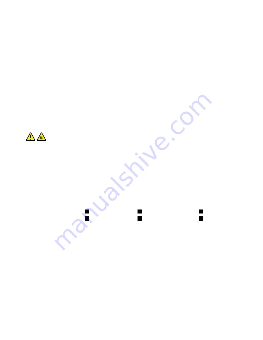
5. Follow the following sequence to remove the four screws that secure the heat sink and fan assembly

to the system board:

a. Partially remove screw

1

, then fully remove screw

2

, and then fully remove screw

1

.

b. Partially remove screw

3

, then fully remove screw

4

, and then fully remove screw

3

.

Note:

Carefully remove the four screws to avoid any possible damage to the system board. The four

screws cannot be removed from the heat sink and fan assembly.

86

P320 User Guide

Содержание THINKSTATION P320 30BG

Страница 1: ...P320 User Guide Machine Types 30BG 30BH and 30BR ...

Страница 2: ... information on page iii and Appendix G Notices on page 119 First Edition March 2017 Copyright Lenovo 2017 LIMITED AND RESTRICTED RIGHTS NOTICE If data or software is delivered pursuant to a General Services Administration GSA contract use reproduction or disclosure is subject to restrictions set forth in Contract No GS 35F 05925 ...

Страница 3: ...formation 20 Cleaning your computer 23 Maintenance 23 Basic maintenance tips 23 Good maintenance practices 23 Keeping your computer current 24 Moving your computer 24 Chapter 4 Security 27 Locking your computer 27 Attaching a padlock 27 Attaching a Kensington style cable lock 28 Attaching a cable lock 29 Viewing and changing security settings in the Setup Utility program 29 Using passwords and Win...

Страница 4: ...bly 94 Rear fan assembly 95 Completing the parts replacement 97 Chapter 8 Getting information help and service 99 Information resources 99 Accessing the user guide in various languages 99 Windows help system 99 Safety and warranty 99 Lenovo Web site 99 Lenovo Support Web site 100 Frequently asked questions 100 Help and service 100 Calling for service 100 Using other services 101 Purchasing additio...

Страница 5: ...ervice Provider who is approved to repair your particular product Note Some computer parts can be upgraded or replaced by the customer Upgrades typically are referred to as options Replacement parts approved for customer installation are referred to as Customer Replaceable Units or CRUs Lenovo provides documentation with instructions when it is appropriate for customers to install options or repla...

Страница 6: ...ace the part on the computer cover or other metal surface Power cords and power adapters Use only the power cords and power adapters supplied by the product manufacturer Do not use the ac power cord for other devices The power cords shall be safety approved For Germany it shall be H05VV F 3G 0 75 mm2 or better For other countries the suitable types shall be used accordingly Never wrap a power cord...

Страница 7: ...out power loads and branch circuit ratings Be sure that the power outlet you are using is properly wired easily accessible and located close to the equipment Do not fully extend power cords in a way that will stress the cords Be sure that the power outlet provides the correct voltage and current for the product you are installing Carefully connect and disconnect the equipment from the electrical o...

Страница 8: ...imal environment in which to use your computer is 10 C 35 C 50 F 95 F with humidity ranging between 35 and 80 If your computer is stored or transported in temperatures less than 10 C 50 F allow the cold computer to rise slowly to an optimal operating temperature of 10 C 35 C 50 F 95 F before use This process could take two hours in extreme conditions Failure to allow your computer to rise to an op...

Страница 9: ...gy levels are present inside any component that has this label attached There are no serviceable parts inside these components If you suspect a problem with one of these parts contact a service technician Cleaning and maintenance Keep your computer and workspace clean Shut down the computer and then disconnect the power cord before cleaning the computer Do not spray any liquid detergent directly o...

Страница 10: ...viii P320 User Guide ...

Страница 11: ...s of your computer hardware Front view Note The computer hardware might look slightly different from the illustrations Figure 1 Front view 1 Optical drive eject close button 2 USB 3 0 connectors 2 3 Hard disk drive activity indicator 4 Power indicator 5 Power button 6 Microphone connector 7 Headset connector 8 Card reader available on some models 1 Optical drive eject close button Press the button...

Страница 12: ...r computer is unresponsive you can turn off the computer by pressing and holding the power button for four or more seconds 6 Microphone connector Use this connector to attach a microphone to your computer when you want to record sound or if you use speech recognition software 7 Headset connector Use this connector to attach a headset to your computer 8 Card reader available on some models This is ...

Страница 13: ... connector 8 PCIe card area different cards provide different connectors 9 Audio line in connector 10 Optional serial connector 11 Cable lock slots 12 Padlock loop 13 Audio line out connector 14 Ethernet connector 15 PS 2 keyboard connector available on some models 16 Security lock slot 1 Power cord connector Connect the power cord to your computer for power supply 2 10 Serial connector Use this c...

Страница 14: ...ht vary 9 Audio line in connector Used to receive audio signals from an external audio device such as a stereo system When you attach an external audio device a cable is connected between the audio line out connector of the device and the audio line in connector of the computer 11 Cable lock slots 2 Used to secure a cable lock For more information see Attaching a cable lock on page 29 12 Padlock l...

Страница 15: ...Preparing your computer and removing the computer cover on page 55 Figure 3 Computer components 1 Heat sink and fan assembly 2 Memory module 3 Optical drive available on some models 4 Card reader available on some models 5 Front audio and USB assembly 6 Front bezel 7 Front fan assembly available on some models 8 Hard disk drives 9 Graphics card available on some models 10 Cover presence switch als...

Страница 16: ...r connectors 14 Thunderbolt connector 15 Parallel connector 16 eSATA connector 17 SATA connectors 18 Power fan connector 19 USB hardware disable header 20 Front bezel connector for connecting LED indicators and the power button 21 Front USB 3 0 connector for connecting USB connectors on the front panel 22 USB 2 0 connectors for connecting the front USB 2 0 connector card reader connector or Blueto...

Страница 17: ...e following illustration shows the locations of the drive bays Note The computer hardware might look slightly different from the illustrations Figure 5 Drive bay locations 1 Primary optical drive bay with an optical drive a flex module a front access storage enclosure a Multi drive Conversion Kit or a Slim Optical Drive Adapter installed in some models 2 Secondary optical drive bay with an optical...

Страница 18: ...roprocessor and memory information about your computer do the following 1 Click the Start button to open the Start menu 2 Depending on your Microsoft Windows operating system version do one of the following For Windows 7 Right click Computer and then click Properties For Windows 10 Click Settings System About To view detailed information about the devices such as the optical drive and network adap...

Страница 19: ...nding on your Windows version do one of the following For Windows 7 Click the Start button to open the Start menu Right click Computer and then click Manage For Windows 10 Right click the Start button to open the Start context menu 2 Click Disk Management and follow the instructions on the screen Video features Integrated graphics supports the following connectors on your computer DisplayPort conn...

Страница 20: ...ystem board on page 6 Power supply Your computer comes with one of the following power supplies 250 watt automatic 85 voltage sensing power supply 400 watt automatic 92 voltage sensing power supply Wireless features Depending on your computer model the following wireless features are supported Wireless LAN Bluetooth System management features Ability to store power on self test POST hardware test ...

Страница 21: ...ot Execution Environment enables you to start computers using a network interface This manner is independent of starting computers from data storage devices such as the hard disk drive or installed operating systems System Management SM basic input output system BIOS and SM software The SM BIOS specification defines data structures and access methods in a BIOS Therefore a user or an application ca...

Страница 22: ...pecifications This section lists the physical specifications for your computer Dimensions Width 175 mm 6 89 inches Height 376 mm 14 80 inches Depth 426 mm 16 77 inches Weight Maximum configuration as shipped 13 kg 28 66 lb Environment Air temperature Operating From 10 C 50 F to 35 C 95 F Storage in original shipping package From 40 C 40 F to 60 C 140 F Storage without package From 10 C 14 F to 60 ...

Страница 23: ...nu Then click the name of the desired program to launch the program 2 If the program name is not displayed on the Start menu access the program from Control Panel a Depending on your Windows version do one of the following For Windows 7 Click Control Panel on the Start menu For Windows 10 Right click the Start button to open the Start context menu and then click Control Panel b View Control Panel ...

Страница 24: ...s 10 The Lenovo PC Experience program helps you work more easily and securely The program provides easy access to Lenovo ThinkVantage Tools or Lenovo Tools important settings and information about your computer the Lenovo Support Web site and so on Lenovo ID Windows 10 The Lenovo ID program enables you to create and manage your Lenovo ID With a Lenovo ID you can connect to everything Lenovo throug...

Страница 25: ... the volume icon in the Windows notification area on the taskbar Note If the volume icon is not displayed in the Windows notification area add the icon to the notification area See the Windows help system 2 Follow the instructions on the screen and the hover text to adjust the volume mute the speaker or unmute the speaker Using a disc This section provides instructions on how to use a disc and the...

Страница 26: ...e help system of the disc player program To remove a disc from the optical drive do the following 1 With the computer on press the eject close button on the front of the optical drive The tray slides out of the drive 2 Carefully remove the disc from the tray 3 Press the eject close button again or gently push the tray forward to close the tray Note If the tray does not slide out of the drive when ...

Страница 27: ... a network Connecting to an Ethernet LAN You can connect your computer to an Ethernet LAN by connecting an Ethernet cable to the Ethernet connector DANGER To avoid the risk of electrical shock do not connect the telephone cable to the Ethernet connector Connecting to a wireless LAN You can connect your computer to a wireless LAN without the use of an Ethernet cable but by means of radio waves only...

Страница 28: ...onnect to a Bluetooth enabled device do the following 1 Turn on the Bluetooth feature of your computer Ensure that the Bluetooth enabled device is located within a distance of about 10 m 32 8 ft from your computer 2 Click the Bluetooth icon in the Windows notification area on the taskbar Then click Add a Device and follow the instructions on the screen Note If the Bluetooth icon is not displayed i...

Страница 29: ... impossible to avoid reflections or to adjust the lighting an antiglare filter placed over the screen might be helpful However these filters might affect the clarity of the image on the screen try them only after you have exhausted other methods of reducing glare Air circulation Your computer produces heat The computer has a fan that pulls in fresh air and forces out hot air through the air vents ...

Страница 30: ...e Accessibility information Lenovo is committed to providing users who have hearing vision and mobility limitations with greater access to information and technology This section provides information about the ways these users can get the most out of their computer experience You also can get the most up to date accessibility information from the following Web site http www lenovo com accessibilit...

Страница 31: ...ast High Contrast is a feature that heightens the color contrast of some text and images on your screen As a result those items are more distinct and easier to identify Personalized keyboard Adjust keyboard settings to make your keyboard easier to use For example you can use your keyboard to control the pointer and type certain key combinations easier Personalized mouse Adjust mouse settings to ma...

Страница 32: ...em size You can make the items on your screen easier to read by changing the item size To change the item size temporarily use the Magnifier tool in Ease of Access Center See Ease of Access Center on page 21 To change the item size permanently do the following Change the size of all the items on your screen 1 Right click a blank area on the desktop 2 Depending on your Windows version do one of the...

Страница 33: ... remember to clean the screen periodically Wipe the screen surface gently with a soft dry cloth or blow on the screen to remove grit and other loose particles Depending on the type of the screen moisten a soft lint free cloth with an LCD cleaner or liquid glass cleaner and then wipe the screen surface Maintenance With appropriate care and maintenance your computer will serve you reliably This sect...

Страница 34: ...section provides instructions on how to get the latest updates for your computer Getting the latest system updates To get the latest system updates for your computer ensure that your computer is connected to the Internet and do one of the following Use the corresponding Lenovo program to get the system updates such as device driver updates software updates and BIOS updates For Windows 7 Use the Sy...

Страница 35: ... computer to another country or region When you move your computer to another country or region you must take local electrical standards into consideration If the local electrical outlet style is different from the type you are using use either an electrical plug adapter or a new power cord To purchase such items contact the Lenovo Customer Support Center For a list of Lenovo Support phone numbers...

Страница 36: ...26 P320 User Guide ...

Страница 37: ...nst viruses on page 31 Computrace Agent software embedded in firmware on page 31 Trusted Platform Module TPM on page 31 Locking your computer This section provides instructions on how to lock your computer with the locking devices to keep your computer safe Attaching a padlock Locking the computer cover helps prevent unauthorized people from gaining access to the inside of your computer Your compu...

Страница 38: ...rear of your computer Depending on the type selected the cable lock can be operated with a key or combination The cable lock also locks the buttons used to open the computer cover This is the same type of lock used with many notebook computers You can order such a cable lock directly from Lenovo by searching for Kensington at http www lenovo com support Figure 8 Kensington style cable lock 28 P320...

Страница 39: ...urity settings in the Setup Utility program do the following 1 Start the Setup Utility program See Starting the Setup Utility program on page 33 2 Select Security 3 Follow the instructions on the right side of the screen to view and change security settings You can refer to Using the Setup Utility program on page 33 to get basic information about some major security settings 4 To save settings and...

Страница 40: ...p Utility program press F10 select Yes in the window displayed and press Enter The cover presence switch connector on the system board is enabled Note For some keyboards you might need to press Fn F10 to exit the Setup Utility program The cover presence switch starts functioning If the switch detects that the computer cover is not correctly installed or closed an error message is displayed when yo...

Страница 41: ...rt menu For Windows 10 Right click the Start button to open the Start context menu 2 Click Control Panel View Control Panel by Large icons or Small icons and then click Windows Firewall 3 Follow the instructions on the screen Protecting data against viruses Your computer is preinstalled with an antivirus program to help you guard against detect and eliminate viruses Lenovo provides a full version ...

Страница 42: ...32 P320 User Guide ...

Страница 43: ...instructions on the right side of the screen The keys used to perform various tasks are displayed at the bottom of the screen Enabling or disabling a device This section provides information about how to enable or disable user access to hardware devices such as USB connectors or storage drives To enable or disable a device do the following 1 Start the Setup Utility program See Starting the Setup U...

Страница 44: ... of the following Press the power button Enable the Wake Up on Alarm feature to make your computer wake up at a set time See Enabling or disabling the automatic power on of your computer on page 33 Enable the After Power Loss feature to make your computer wake up when the power supply resumes after a sudden loss of electricity To enable the After Power Loss feature do the following 1 Start the Set...

Страница 45: ...uch as storage drives or memory modules an error message is displayed To enable or disable the configuration change detection do the following 1 Start the Setup Utility program See Starting the Setup Utility program on page 33 2 Select Security Configuration Change Detection and press Enter 3 Select the desired setting and press Enter 4 To save settings and exit the Setup Utility program press F10...

Страница 46: ...tup Utility program cannot be accessed until a valid password is entered If both the power on password and administrator password are set you can enter either password However you must use your administrator password to change any configuration settings Hard disk password Setting a hard disk password prevents unauthorized access to the data on the internal storage drive such as a hard disk drive W...

Страница 47: ...e the Clear Complementary Metal Oxide Semiconductor CMOS Recovery jumper on the system board See Parts on the system board on page 6 4 Move the jumper from the standard position pin 1 and pin 2 to the maintenance position pin 2 and pin 3 5 Reinstall the computer cover and connect the power cord See Installing or replacing hardware on page 56 6 Turn on the computer and leave it on for approximately...

Страница 48: ...manent startup device see Changing the startup device sequence permanently on page 37 Exiting the Setup Utility program To exit the Setup Utility program do one of the following If you want to save the new settings press F10 or Fn F10 depending on the keyboard Then select Yes in the window displayed and press Enter If you do not want to save the new settings select Exit Discard Changes and Exit an...

Страница 49: ...BIOS update disc into the optical drive Wait a few minutes The recovery process begins After the recovery process is completed your computer will shut down automatically Note If the computer does not start up from the disc select the disc as the startup device See Selecting a temporary startup device on page 38 9 Repeat steps 1 4 10 Move the Clear CMOS Recovery jumper back to the standard position...

Страница 50: ...se the arrow keys to select a Stripe Size in the Stripe Size field and press Tab 6 Type a volume size in the Capacity field and press Tab 7 Press Enter to initiate volume creation 8 When prompted press Y to accept the warning message and create the volume 9 Return to step 2 to create additional RAID volumes or select Exit and press Enter 10 Press Y when prompted to confirm the exit Deleting RAID v...

Страница 51: ...pace key to mark individual physical hard disk drives to be reset and then press Enter to complete the selection 4 When prompted press Y to confirm the reset action 5 After resetting your hard disk drives to non RAID you can See Deleting RAID volumes on page 40 for RAID volume deletion See Creating RAID volumes on page 40 for RAID volume creation Use the up and down arrow keys to select Exit and p...

Страница 52: ...42 P320 User Guide ...

Страница 53: ...ected by a virus If the program detects a virus remove the virus If the antivirus program does not resolve your problem continue with the next step 3 Go to Troubleshooting on page 43 and follow the instructions for the type of problem you are experiencing If these troubleshooting instructions do not resolve your problem continue with the next step 4 Run the diagnostic program See Diagnosing proble...

Страница 54: ...ick the volume icon in the Windows notification area on the taskbar Ensure that the mute speakers settings are not selected and none of the volume settings is set too low Note If the volume icon is not displayed in the Windows notification area add the icon to the notification area See the Windows help system For some computers that have a front audio panel ensure that the volume is not set too lo...

Страница 55: ...ng the disc into the other drive In some cases only one of the drives is connected to the audio subsystem A bootable recovery medium such as the Product Recovery CD cannot be used to start your computer Solution Ensure that the CD or DVD drive is set as the top priority of the Boot Priority Order in the Setup Utility program Refer to Selecting a temporary startup device on page 38 for information ...

Страница 56: ...at If Small Computer System Interface SCSI devices are installed ensure that the last external device in each SCSI chain is terminated correctly For more information see your SCSI documentation Storage drive problems Some or all storage drives are missing from the Setup Utility program Solutions Ensure that the signal cables and power cables for all the storage drives are connected correctly If th...

Страница 57: ...rking software Set the same duplex for the switch port and the adapter If you configured the adapter for full duplex ensure that the switch port is also configured for full duplex Setting the wrong duplex mode might degrade performance cause data loss or result in lost connections When a Gigabit Ethernet model computer is used at a speed of 1000 Mbps the Ethernet LAN connection fails or errors occ...

Страница 58: ... Utility program on page 33 Turn on the Bluetooth radios Enable the Bluetooth adapter 1 Depending on your Windows version do one of the following For Windows 7 Click the Start button to open the Start menu For Windows 10 Right click the Start button to open the Start context menu 2 Click Control Panel View Control Panel by Large icons or Small icons and then click Network and Sharing Center Change...

Страница 59: ...ree storage drive space is insufficient Solutions Free up the storage drive space Clean out your Inbox Sent Items and Deleted Items folders from your e mail application Clean up your C drive 1 Click the Start button to open the Start menu 2 Depending on your Windows version do one of the following For Windows 7 Click Computer For Windows 10 Click File Explorer This PC 3 Right click your C drive an...

Страница 60: ...e online Install any programs supplied with the serial device Refer to the documentation that comes with the serial device for more information If you added one serial connector adapter ensure that the adapter is installed correctly USB device problems A USB device cannot be accessed Solutions Connect the USB cable from the USB connector to the USB device If the USB device has its own power cord c...

Страница 61: ...puter current on page 24 Diagnosing problems Many computer problems can be solved without outside assistance If you experience a problem with your computer the first place to start is the troubleshooting information in your computer documentation If you suspect a software problem see the documentation including readme files and help information systems that come with the operating system or progra...

Страница 62: ...e Lenovo Companion help system Recovery information This section provides instructions on how to recover your operating system Note If a device does not work correctly after recovering the operating system update the device driver See Keeping your computer current on page 24 Recovery information for Windows 7 To recover your Windows 7 operating system use the following solutions Use Windows recove...

Страница 63: ...tore 3 Follow the instructions on the screen Use the File History tool to restore your files from a backup Note If you use the File History tool to restore your files from a backup ensure that you backed up your data earlier with the tool 1 Right click the Start button to open the Start context menu 2 Click Control Panel View Control Panel by Large icons or Small icons and then click File History ...

Страница 64: ...54 P320 User Guide ...

Страница 65: ...etal surface on the computer for at least two seconds This reduces static electricity from the package and your body before you install or replace a new part When possible remove the new part from the static protective package and install it directly in the computer without setting the part down When this is not possible place the static protective package on a smooth level surface and place the p...

Страница 66: ...mputer parts provided only by Lenovo When installing or replacing an option use the appropriate instructions in this section along with the instructions that come with the option In most areas of the world Lenovo requires the return of the defective CRU Information about this will come with the CRU or will come a few days after the CRU arrives External options You can connect external options to y...

Страница 67: ...the chassis Then pivot the front bezel inwards until it snaps into position on the left side What to do next To work with another piece of hardware go to the appropriate section To complete the installation or replacement go to Completing the parts replacement on page 97 PCIe card Attention Do not open your computer or attempt any repair before reading and understanding the Read this first Importa...

Страница 68: ...2 At the rear of the computer press the release button 1 to open the card latch 2 Figure 12 Opening the PCIe card latch 58 P320 User Guide ...

Страница 69: ... removed from the slot b If the card is held in place by a retaining latch press the card retaining latch as shown to disengage the latch Then grasp the card and gently pull it out of the slot Figure 14 Disengaging the card retaining latch 4 Remove the new PCIe card from its static protective package 5 Install the new card into the appropriate slot on the system board See Parts on the system board...

Страница 70: ...ing and understanding the Read this first Important safety information on page iii To install or replace an M 2 solid state drive do the following 1 Prepare your computer See Preparing your computer and removing the computer cover on page 55 2 Lay the computer on its side for easier access to the system board 3 Depending on whether you are installing or replacing an M 2 solid state drive do one of...

Страница 71: ... drive is secured by a retention latch Pull the handle of the retention latch outward to release the M 2 solid state drive Then gently pull the M 2 solid state drive out of the M 2 slot Figure 17 Removing the M 2 solid state drive If you are installing an M 2 solid state drive pull outward the handle of the retention latch in the M 2 solid state drive adapter 4 Ensure that a thermal pad is placed ...

Страница 72: ...hole to secure the new drive Figure 19 Installing the M 2 solid state drive 6 Position the heat sink on the M 2 solid state drive adapter Ensure that the two mounting studs in the heat sink are aligned with the holes in the M 2 solid state drive adapter Then push the mounting studs downward to secure the heat sink to the adapter 62 P320 User Guide ...

Страница 73: ...ent go to Completing the parts replacement on page 97 Memory module Attention Do not open your computer or attempt any repair before reading and understanding the Read this first Important safety information on page iii Your computer has four memory slots for installing or replacing DDR4 DIMMs that provide up to a maximum of 64 GB system memory When installing or replacing a memory module use the ...

Страница 74: ...Lay the computer on its side for easier access to the system board 3 Locate the memory slots See Parts on the system board on page 6 4 Remove any parts that might prevent your access to the memory slots Depending on your computer model you might need to remove the PCIe x16 graphics card for easier access to the memory slots See PCIe card on page 57 5 Depending on whether you are installing or repl...

Страница 75: ...emory module out of the memory slot Figure 22 Removing a memory module If you are installing a memory module open the retaining clips of the memory slot into which you want to install the memory module Figure 23 Opening the retaining clips Chapter 7 Hardware installation and replacement 65 ...

Страница 76: ...on Do not open your computer or attempt any repair before reading and understanding the Read this first Important safety information on page iii Note For some computer models the optical drive bay might be installed with an optical drive a Multi drive Conversion Kit or a Slim Optical Drive Adapter To install or replace an optical drive do the following 1 Prepare your computer See Preparing your co...

Страница 77: ...tical drive retainer from the computer If you are replacing an optical drive do the following a Disconnect cables from the rear of the optical drive press the release button 1 and then slide the optical drive out of the chassis Figure 26 Removing the optical drive b Remove the optical drive retainer from the left side of the optical drive Chapter 7 Hardware installation and replacement 67 ...

Страница 78: ...ay from the front of the computer until the optical drive snaps into position Figure 28 Installing the optical drive 6 Connect the cables to the rear of the new optical drive Figure 29 Connecting the cables to the rear of the new optical drive 7 If you are installing a new optical drive remove the plastic panel in the front bezel for the desired drive bay 68 P320 User Guide ...

Страница 79: ...connection see Preparing your computer and removing the computer cover on page 55 and Parts on the system board on page 6 for more information The operating system of your computer does not reside on the hard disk drive installed in the front access storage enclosure Attention If any of the above requirements are not met do not install or replace the hard disk drive when the computer is turned on ...

Страница 80: ...d disk drive from the bracket 5 Flex both sides of the bracket and align pins 1 on the bracket with the corresponding holes in the new hard disk drive Do not touch the circuit board on the hard disk drive Note Ensure that the circuit board faces downward and the connectors face toward the rear of the bracket Figure 33 Installing the hard disk drive into the bracket 70 P320 User Guide ...

Страница 81: ...pair before reading and understanding the Read this first Important safety information on page iii The Multi drive Conversion Kit hereafter referred to as kit might be equipped with either one or both of the following components Slim optical drive Internal storage drive such as hard disk drive solid state drive or hybrid drive Slim optical drive To install or replace a slim optical drive in the ki...

Страница 82: ... optical drive from the kit b Pull the bracket as shown to remove it from the slim optical drive Figure 36 Removing the bracket from the slim optical drive 3 Align the three tabs on the bracket with the corresponding holes in the new slim optical and install the bracket to the new slim optical drive Figure 37 Installing the bracket to the new slim optical drive 72 P320 User Guide ...

Страница 83: ...storage drive To install or replace a 3 5 inch internal storage drive in the kit do the following 1 Slide the kit out of the chassis See Optical drive on page 66 2 Press the clip as shown to open the rear cover of the kit Figure 39 Opening the kit from the rear 3 If you are replacing an old 3 5 inch internal storage drive do the following Chapter 7 Hardware installation and replacement 73 ...

Страница 84: ...e 40 Removing the 3 5 inch internal storage drive from the rear b Flex both sides of the bracket to remove the 3 5 inch internal storage drive from the bracket Do not touch the circuit board 1 on the internal storage drive Figure 41 Flexing both sides of the bracket to remove the 3 5 inch internal storage drive 74 P320 User Guide ...

Страница 85: ...acket Do not touch the circuit board 5 on the internal storage drive Figure 42 Installing the new 3 5 inch internal storage drive into the bracket 5 Slide the new 3 5 inch internal storage drive into the kit from the rear until the internal storage drive snaps into position Figure 43 Sliding the new 3 5 inch internal storage drive into the kit Chapter 7 Hardware installation and replacement 75 ...

Страница 86: ...storage drive To install or replace a 2 5 inch internal storage drive in the kit do the following 1 Slide the kit out of the chassis See Optical drive on page 66 2 Press the clip as shown to open the rear cover of the kit Figure 45 Opening the kit from the rear 3 If you are replacing an old 2 5 inch internal storage drive do the following 76 P320 User Guide ...

Страница 87: ...of the kit Figure 46 Removing the 2 5 inch internal storage drive from the rear b Flex both sides of the bracket to remove the 2 5 inch internal storage drive from the bracket Figure 47 Flexing both sides of the bracket to remove the 2 5 inch internal storage drive Chapter 7 Hardware installation and replacement 77 ...

Страница 88: ...rive into the bracket Do not touch the circuit board 5 on the internal storage drive Figure 48 Installing the new 2 5 inch internal storage drive into the bracket 5 Slide the new 2 5 inch internal storage drive into the kit from the rear until the internal storage drive snaps into position Figure 49 Sliding the new 2 5 inch internal storage drive into the kit 78 P320 User Guide ...

Страница 89: ...torage drive To replace a 3 5 inch internal storage drive with a 2 5 inch internal storage drive do the following 1 Ensure that the 3 5 inch internal storage drive is removed from the bracket first See 3 5 inch internal storage drive on page 73 2 Remove three pins 1 and install them into slots 2 Figure 51 Removing three pins and installing them into new slots Chapter 7 Hardware installation and re...

Страница 90: ...3 Pivot the bracket as shown to release both tabs 1 and 3 from the slots Figure 52 Pivoting the bracket 4 Fold the bracket as shown Figure 53 Folding the bracket 80 P320 User Guide ...

Страница 91: ...ge 76 Replacing a 2 5 inch internal storage drive with a 3 5 inch internal storage drive To replace a 2 5 inch internal storage drive with a 3 5 inch internal storage drive do the following 1 Ensure that the 2 5 inch internal storage drive is removed from the bracket See 2 5 inch internal storage drive on page 76 2 Remove three pins 1 and install them into slots 2 Figure 55 Removing three pins 1 a...

Страница 92: ...3 Release tabs 1 2 and 3 from the corresponding slots Figure 56 Releasing tabs 1 2 and 3 from the corresponding slots 4 Unfold the bracket as shown Figure 57 Unfolding the bracket 82 P320 User Guide ...

Страница 93: ...type of memory that maintains the date time and settings for built in features A battery keeps this information active when you turn off the computer The battery normally requires no charging or maintenance throughout its life however no battery lasts forever If the battery fails the date time and configuration information including passwords are lost An error message is displayed when you turn on...

Страница 94: ... date time and any passwords See Using the Setup Utility program on page 33 What to do next To work with another piece of hardware go to the appropriate section To complete the installation or replacement go to Completing the parts replacement on page 97 Power supply assembly Attention Do not open your computer or attempt any repair before reading and understanding the Read this first Important sa...

Страница 95: ...y do the following 1 Prepare your computer See Preparing your computer and removing the computer cover on page 55 2 Disconnect the power supply assembly cables from the system board and all drives See Parts on the system board on page 6 3 Release the power supply assembly cables from the cable clips and ties 4 Lay the computer on its side and remove the four screws at the rear of the chassis that ...

Страница 96: ...e heat sink and fan assembly might be very hot Before you open the computer cover turn off the computer and wait several minutes until the computer is cool To replace the heat sink and fan assembly do the following 1 Prepare your computer See Preparing your computer and removing the computer cover on page 55 2 Lay the computer on its side for easier access to the system board 3 Locate the heat sin...

Страница 97: ...ur screws to secure the new heat sink and fan assembly Do not over tighten the screws a Partially tighten screw 1 then fully tighten screw 2 and then fully tighten screw 1 b Partially tighten screw 3 then fully tighten screw 4 and then fully tighten screw 3 9 Connect the heat sink and fan assembly cable to the microprocessor fan connector on the system board See Parts on the system board on page 6...

Страница 98: ...drive from the drive cage Figure 63 Removing the primary hard disk drive 5 Flex the sides of the bracket to remove the hard disk drive from the bracket 6 To install a new hard disk drive into the bracket flex the bracket and align pin 1 pin 2 pin 3 and pin 4 on the bracket with the corresponding holes in the hard disk drive Do not touch the circuit board 5 on the bottom of the hard disk drive Figu...

Страница 99: ...es with a secondary storage drive bay for installing or replacing a secondary 3 5 inch hard disk drive or a 2 5 inch solid state drive To replace the secondary hard disk drive do the following 1 Prepare your computer See Preparing your computer and removing the computer cover on page 55 2 Locate the secondary hard disk drive See Computer components on page 5 3 Disconnect the signal cable and the p...

Страница 100: ...naps into position Figure 68 Installing the secondary hard disk drive 8 Connect the signal cable and the power cable to the new hard disk drive What to do next To work with another piece of hardware go to the appropriate section To complete the installation or replacement go to Completing the parts replacement on page 97 Solid state drive The solid state drive is only available on some models Atte...

Страница 101: ...ve Then install the four screws to secure the solid state drive to the storage converter Figure 69 Installing the solid state drive into the storage converter 3 Remove the 3 5 inch storage drive bracket out of the chassis 4 To install the storage converter into the 3 5 inch storage drive bracket flex the bracket and align pin 1 pin 2 pin 3 and pin 4 on the bracket with the corresponding holes in t...

Страница 102: ...llowing 1 Prepare your computer See Preparing your computer and removing the computer cover on page 55 2 Locate the desired storage drive bay See Internal drives on page 7 3 Disconnect the signal cable and power cable from the solid state drive 4 Remove the storage converter with the solid state drive from the storage drive bay See Primary hard disk drive on page 87 or Secondary hard disk drive on...

Страница 103: ...emoving the solid state drive from the storage converter 7 Install a new solid state drive into the storage converter Then install the four screws to secure the new solid state drive to the storage converter Figure 73 Installing the new solid state drive into the storage converter Chapter 7 Hardware installation and replacement 93 ...

Страница 104: ...ext To work with another piece of hardware go to the appropriate section To complete the installation or replacement go to Completing the parts replacement on page 97 Front fan assembly Attention Do not open your computer or attempt any repair before reading and understanding the Read this first Important safety information on page iii Note The front fan assembly is only available on some models T...

Страница 105: ...the holes 6 Pull the tips of the rubber mounts until the front fan assembly is secured in place Figure 76 Installing the front fan assembly 7 Connect the front fan assembly cable to the power fan connector on the system board What to do next To work with another piece of hardware go to the appropriate section To complete the installation or replacement go to Completing the parts replacement on pag...

Страница 106: ...aking or cutting the rubber mounts and gently pulling the rear fan assembly out of the chassis Note The new rear fan assembly comes with four new rubber mounts attached Figure 77 Removing the rear fan assembly 5 Install the new rear fan assembly by aligning the new rubber mounts with the corresponding holes in the chassis Push the rubber mounts through the holes 6 Pull on the tips of the rubber mo...

Страница 107: ... no tools or loose screws are left inside your computer See Computer components on page 5 for the locations of various components in your computer 2 Ensure that the cables are routed correctly before reinstalling the computer cover Keep cables clear of the hinges and sides of the computer chassis to avoid interference with reinstalling the computer cover 3 Position the computer cover on the chassi...

Страница 108: ...er See Hardware locations on page 1 8 Update the configuration of your computer if necessary See Using the Setup Utility program on page 33 9 If a newly installed hardware component does not work correctly update the device driver See Keeping your computer current on page 24 98 P320 User Guide ...

Страница 109: ...anty and Setup Guide provided with your computer contains important safety information product warranty terms initial setup procedure and legal notices Ensure that you read and understand all safety information in the Safety Warranty and Setup Guide before using your computer In addition read and understand Read this first Important safety information on page iii before using your computer This pr...

Страница 110: ...ovided contact your Lenovo reseller or Lenovo marketing representative The following services are available during the warranty period Problem determination Trained service personnel are available to assist you with determining a hardware problem and deciding what action is necessary to fix the problem Hardware repair If the problem is caused by hardware under warranty trained service personnel ar...

Страница 111: ... of a particular machine type In some countries fees and restrictions might apply at the time of service To determine whether your computer is eligible for International Warranty Service and to view a list of the countries or regions where service is available go to http www lenovo com support For technical assistance with the installation of or questions related to Service Packs for your preinsta...

Страница 112: ...102 P320 User Guide ...

Страница 113: ... the system memory modules Memory module type DDR4 UDIMM Memory module operating voltage 1 2 V Memory module frequency 2400 MT s Microprocessor model Intel Xeon For models with the Windows 10 operating system E3 1280 v6 E3 1275 v6 E3 1270 v6 E3 1245 v6 E3 1240 v6 E3 1230 v6 E3 1225 v6 E3 1220 v6 For models with the Window 7 operating system E3 1245 v5 E3 1240 v5 E3 1230 v5 E3 1225 v5 E3 1220 v5 In...

Страница 114: ...104 P320 User Guide ...

Страница 115: ...ovo office or reseller to obtain a printed version of the LLW Accessing the Ubuntu help system The Ubuntu help system provides information about how to use the Ubuntu operating system To access the help system from the Unity move your pointer to the Launch bar and then click the Help icon If you cannot find the Help icon from the Launch bar click the Search icon and type Help to search it To learn...

Страница 116: ...106 P320 User Guide ...

Страница 117: ...his equipment does cause harmful interference to radio or television reception which can be determined by turning the equipment off and on the user is encouraged to try to correct the interference by one or more of the following measures Reorient or relocate the receiving antenna Increase the separation between the equipment and receiver Connect the equipment into an outlet on a circuit different ...

Страница 118: ...forderungen der EU Richtlinie 2014 30 EU zur Angleichung der Rechtsvorschriften über die elektromagnetische Verträglichkeit in den EU Mitgliedsstaaten und hält die Grenzwerte der Klasse B der Norm gemäß Richtlinie Um dieses sicherzustellen sind die Geräte wie in den Handbüchern beschrieben zu installieren und zu betreiben Des Weiteren dürfen auch nur von der Lenovo empfohlene Kabel angeschlossen w...

Страница 119: ...e power mains with rated current less than or equal to 20 A per phase Japan notice for ac power cord The ac power cord shipped with your product can be used only for this specific product Do not use the ac power cord for other devices Lenovo product service information for Taiwan Keyboard and mouse compliance statement for Taiwan Eurasian compliance mark Brazil audio notice Ouvir sons com mais de ...

Страница 120: ... su operación no deseada Additional regulatory information For additional regulatory information refer to the Regulatory Notice shipped with your computer Depending on the configuration of your computer and the country or region where the computer was purchased you might have received additional printed regulatory notices All regulatory notices are available on the Lenovo Support Web site in elect...

Страница 121: ...he WEEE marking must not dispose of end of life EEE as unsorted municipal waste but use the collection framework available to them for the return recycle and recovery of WEEE and to minimize any potential effects of EEE on the environment and human health due to the presence of hazardous substances Lenovo electrical and electronic equipment EEE may contain parts and components which at end of life...

Страница 122: ...eries from Lenovo computers A button shaped lithium battery is installed inside your Lenovo computer to provide power to the computer clock while the computer is off or disconnected from the main power source If you need to replace it with a new one contact your place of purchase or contact Lenovo for service If you need to dispose of a disused lithium battery insulate it with vinyl tape contact y...

Страница 123: ...ccumulators on the environment and human health due to the potential presence of hazardous substances Before placing electrical and electronic equipment EEE in the waste collection stream or in waste collection facilities the end user of equipment containing batteries and or accumulators must remove those batteries and accumulators for separate collection Disposing of lithium batteries and battery...

Страница 124: ...114 P320 User Guide ...

Страница 125: ...triction of the use of certain hazardous substances in electrical and electronic equipment RoHS recast or RoHS 2 For more information about Lenovo worldwide compliance on RoHS go to http www lenovo com social_responsibility us en RoHS_Communication pdf China RoHS Turkish RoHS The Lenovo product meets the requirements of the Republic of Turkey Directive on the Restriction of the Use of Certain Haza...

Страница 126: ...Ukraine RoHS India RoHS RoHS compliant as per E Waste Management Handling Rules Taiwan RoHS 116 P320 User Guide ...

Страница 127: ...n of greenhouse gas emissions For more information about ENERGY STAR go to http www energystar gov Lenovo encourages you to make efficient use of energy an integral part of your day to day operations To help in this endeavor set the following power management features to take effect when your computer has been inactive for a specified duration Table 1 ENERGY STAR power management features Windows ...

Страница 128: ...118 P320 User Guide ...

Страница 129: ...he publication Lenovo may make improvements and or changes in the products and or the programs described in this publication at any time without notice The products described in this document are not intended for use in implantation or other life support applications where malfunction may result in injury or death to persons The information contained in this document does not affect or change Leno...

Страница 130: ...120 P320 User Guide ...

Страница 131: ...Intel Intel Xeon Intel Core Intel Pentiumare and Thunderbolt are trademarks of Intel Corporation in the U S and or other countries Linux is a registered trademark of Linus Torvalds DisplayPort and Mini DisplayPort are trademarks of the Video Electronics Standards Association Android is a trademark of Google Inc Ubuntu is a registered trademark of Canonical Ltd Other company product or service name...

Страница 132: ...122 P320 User Guide ...

Страница 133: ......

Страница 134: ......

Отзывы: