Lenovo ThinkCentre 4167 Скачать руководство пользователя страница 53

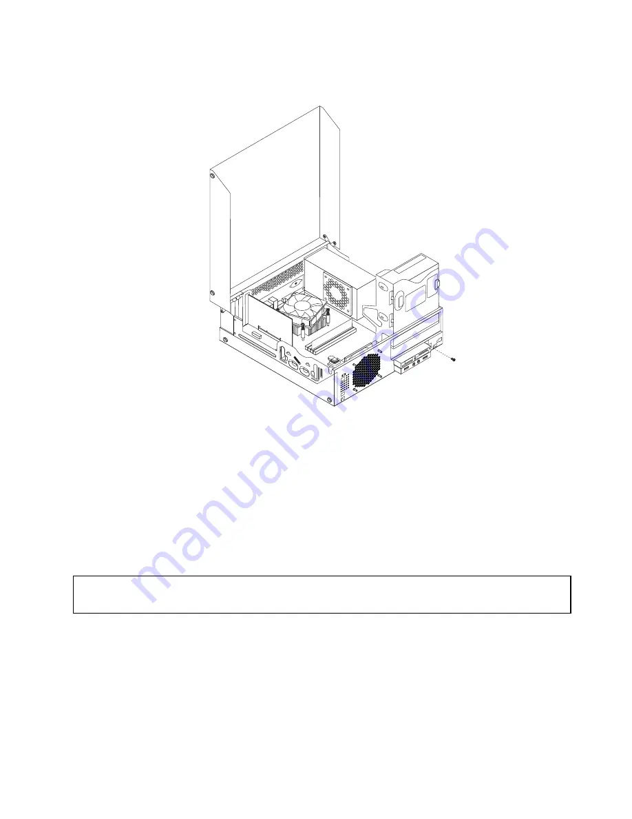
10. Install the screw to secure the card reader bracket to the chassis.

Figure 21. Installing the screw that secures the card reader

11. Pivot the optical drive bay upward and reconnect the card reader cable to one of the USB connectors

on the system board. See “Locating parts on the system board” on page 12.

12. Reinstall the front bezel. See “Removing and reinstalling the front bezel” on page 30.

What to do next:

• To work with another piece of hardware, go to the appropriate section.

• To complete the installation or replacement, go to “Completing the parts replacement” on page 67.

Replacing the battery

Attention:

Do not open your computer or attempt any repair before reading and understanding the “Important safety information”
on page v
.

Your computer has a special type of memory that maintains the date, time, and settings for built-in features,
such as parallel-port assignments (configuration). A battery keeps this information active when you turn
off the computer.

The battery normally requires no charging or maintenance throughout its life; however, no battery lasts
forever. If the battery fails, the date, time, and configuration information (including passwords) are lost. An
error message is displayed when you turn on the computer.

Refer to the “Lithium battery notice” in the

ThinkCentre Safety and Warranty Guide

for information about

replacing and disposing of the battery.

Chapter 5

.

Installing or replacing hardware

41

Содержание ThinkCentre 4167

Страница 1: ...ThinkCentre User Guide Machine Types 0267 0385 1981 4167 5025 5032 5049 5070 and 7518 ...

Страница 2: ...tion on page v and Appendix A Notices on page 115 Fourth Edition June 2012 Copyright Lenovo 2011 2012 LIMITED AND RESTRICTED RIGHTS NOTICE If data or software is delivered pursuant a General Services Administration GSA contract use reproduction or disclosure is subject to restrictions set forth in Contract No GS 35F 05925 ...

Страница 3: ... your computer 21 Accessibility and comfort 21 Arranging your workspace 21 Comfort 21 Glare and lighting 22 Air circulation 22 Electrical outlets and cable lengths 22 Register your computer with Lenovo 23 Moving your computer to another country or region 23 Voltage selection switch 23 Replacement power cords 23 Chapter 4 Security 25 Security features 25 Attaching an integrated cable lock 26 Using ...

Страница 4: ...isc 83 Updating flashing the BIOS from your operating system 84 Recovering from a POST BIOS update failure 84 Chapter 9 Preventing problems 85 Keeping your computer current 85 Getting the latest device drivers for your computer 85 Updating your operating system 85 Using System Update 86 Cleaning and maintenance 86 Basics 86 Cleaning your computer 87 Good maintenance practices 88 Moving your comput...

Страница 5: ...rmation 119 Appendix C WEEE and recycling information 121 Important WEEE Information 121 Recycling information 121 Recycling information for Brazil 122 Battery recycling information for Taiwan 122 Battery recycling information for the European Union 123 Appendix D Restriction of Hazardous Substances Directive RoHS 125 China RoHS 125 Turkish RoHS 125 Ukraine RoHS 125 India RoHS 126 Index 127 Copyri...

Страница 6: ...iv ThinkCentre User Guide ...

Страница 7: ... installation are referred to as Customer Replaceable Units or CRUs Lenovo provides documentation with instructions when it is appropriate for customers to install options or replace CRUs You must closely follow all instructions when installing or replacing parts The Off state of a power indicator does not necessarily mean that voltage levels inside a product are zero Before you remove the covers ...

Страница 8: ...ng so can stress the cord in ways that can cause the cord to fray crack or crimp This can present a safety hazard Always route power cords so that they will not be walked on tripped over or pinched by objects Protect power cord and power adapters from liquids For instance do not leave your power cord or power adapter near sinks tubs toilets or on floors that are cleaned with liquid cleansers Liqui...

Страница 9: ...ou might damage your computer To avoid possible damage to attached devices wait at least five seconds after the computer is shut down to disconnect external devices Heat and product ventilation Computers power adapters and many accessories can generate heat when turned on and when batteries are charging Always follow these basic precautions Do not leave your computer power adapter or accessories i...

Страница 10: ...sunshine Keep electrical appliances such as an electric fan radio high powered speakers air conditioner and microwave oven away from your computer because the strong magnetic fields generated by these appliances can damage the monitor and data on the hard disk drive Do not place any beverages on top of or beside the computer or other attached devices If liquid is spilled on or in the computer or a...

Страница 11: ...ot view directly with optical instruments and avoid direct exposure to the beam Power supply statement Never remove the cover on a power supply or any part that has the following label attached Hazardous voltage current and energy levels are present inside any component that has this label attached There are no serviceable parts inside these components If you suspect a problem with one of these pa...

Страница 12: ...x ThinkCentre User Guide ...

Страница 13: ...sor Memory Your computer supports up to four double data rate 3 unbuffered dual inline memory modules DDR3 UDIMMs Internal drives Optical drive DVD ROM or DVD R optional Serial Advanced Technology Attachment SATA hard disk drive SATA solid state drive Note Your computer supports SATA 2 0 and SATA 3 0 devices For more information see Locating parts on the system board on page 12 Video subsystem Int...

Страница 14: ...data storage devices such as the hard disk drive or installed operating systems Smart Performance Choice The Smart Performance Choice function enables your computer to run with better acoustic performance or better thermal performance See Smart performance choices on page 81 System Management SM Basic Input Output System BIOS and SM software The SM BIOS specification defines data structures and ac...

Страница 15: ...s One PCI Express x1 card slot One PCI Express x16 graphics card slot Power supply Your computer comes with 240 watt automatic voltage sensing power supply Security features Computrace Agent software embedded in firmware Cover presence switch also called intrusion switch Ability to enable or disable a device Ability to enable and disable USB connectors individually Keyboard with fingerprint reader...

Страница 16: ... 140 F without package Humidity Operating 20 to 80 non condensing Storage 20 to 90 non condensing Altitude Operating 50 to 10 000 ft 15 2 to 3 048 m Storage 50 to 35 000 ft 15 2 to 10 668 m Electrical input Input voltage Low range Minimum 100 V ac Maximum 127 V ac Input frequency range 50 to 60 Hz High range Minimum 200 V ac Maximum 240 V ac Input frequency range 50 to 60 Hz 1 The operating system...

Страница 17: ...am name Icon name in Lenovo ThinkVantage Tools Create Recovery Media Factory Recovery Disks Fingerprint Software Fingerprint Reader Lenovo Solution Center or Lenovo ThinkVantage Toolbox System Health and Diagnostics ThinkVantage Password Manager Password Vault ThinkVantage Power Manager Power Controls ThinkVantage Rescue and Recovery Enhanced Backup and Restore ThinkVantage System Update Update an...

Страница 18: ...ar with the innovative technologies provided by Lenovo and get more information about your computer See Lenovo ThinkVantage Toolbox on page 109 for detailed information Product Recovery The Product Recovery program enables you to restore the contents of the hard disk drive to the factory default settings ThinkVantage Client Security Solution The ThinkVantage Client Security Solution program is ava...

Страница 19: ...Start All Programs Lenovo ThinkVantage Tools and double click Enhanced Backup and Restore 2 Follow the instructions on the screen 3 When the installation process completes the Enhanced Backup and Restore icon is activated ThinkVantage System Update The ThinkVantage System Update program helps you keep the software on your computer up to date by downloading and installing software packages ThinkVan...

Страница 20: ...ive eject close button 5 USB connector USB port 2 2 Power switch 6 Microphone connector 3 Hard disk drive activity indicator 7 Headphone connector 4 Power indicator 8 USB connector USB port 1 Locating connectors on the rear of your computer Figure 2 Rear connector locations on page 9 shows the locations of the connectors on the rear of your computer Some connectors on the rear of your computer are...

Страница 21: ...ternal audio device such as a stereo system When you attach an external audio device a cable is connected between the audio line out connector of the device and the audio line in connector of the computer Audio line out connector Used to send audio signals from the computer to external devices such as powered stereo speakers speakers with built in amplifiers headphones multimedia keyboards or the ...

Страница 22: ...uses a PS 2 keyboard connector PS 2 mouse connector optional Used to attach a mouse a trackball or other pointing devices that use a PS 2 mouse connector USB connector Used to attach a device that requires a USB connector such as a USB keyboard a USB mouse a USB scanner or a USB printer If you have more than eight USB devices you can purchase a USB hub which you can use to connect additional USB d...

Страница 23: ...Figure 3 Component locations 1 Heat sink and fan assembly 7 System fan assembly 2 Power supply assembly 8 Internal speaker installed in some models 3 Memory module 9 Cover presence switch Intrusion switch 4 Optical drive 10 Hard disk drive or solid state drive 5 Front audio and USB assembly 11 PCI card installed in some models 6 Front bezel 12 Heat sink fan duct Chapter 1 Product overview 11 ...

Страница 24: ...t 2 DIMM2 19 Front USB connector 2 for connecting additional USB devices 6 Memory slot 3 DIMM3 20 Serial COM2 connector 7 Memory slot 4 DIMM4 21 Internal speaker connector 8 Thermal sensor connector 22 Front audio connector 9 24 pin power connector 23 PCI card slots 2 10 Battery 24 PCI Express x1 card slot 11 Clear CMOS Complementary Metal Oxide Semiconductor Recovery jumper 25 PCI Express x16 gra...

Страница 25: ...ppropriate section in Chapter 5 Installing or replacing hardware on page 29 for instructions on how to install or replace internal drives for your computer Figure 5 Drive bay locations on page 13 shows the locations of the drive bays Figure 5 Drive bay locations 1 Bay 1 Optical drive bay with an optical drive installed in some models 2 Bay 2 Card reader drive bay 3 Bay 3 SATA hard disk drive bay f...

Страница 26: ...The following is a sample of the machine type and model label Figure 6 Machine type and model label 14 ThinkCentre User Guide ...

Страница 27: ...t be prompted to change discs Where can I find help about the Windows operating system The Windows Help and Support information system provides you detailed information about using the Windows operating system to help you get the most of your computer To access the Windows Help and Support information system click Start Help and Support Using the keyboard Depending on your model your computer come...

Страница 28: ... has the following controls 1 Primary mouse button Use this button to select or start a program or menu item 2 Wheel Use the wheel to control the scrolling action of the mouse The direction in which you rotate the wheel controls the direction of the scrolling action 3 Secondary mouse button Use this button to display a menu for the active program icon or object You can switch the function of the p...

Страница 29: ... on or off and change the volume behaviors from Off to On 4 Click OK to save the new settings To add the volume icon to the taskbar on the Windows Vista operating system do the following 1 From the Windows desktop click Start Control Panel Appearance and Personalization 2 In the Taskbar and Start Menu topic click Customize icons on the taskbar 3 On the Notification Area tab select Volume to allow ...

Страница 30: ... open the tray 2 With the tray fully extended insert the CD or DVD into the tray Some DVD drives have a snap hub in the center of the tray If your drive has a snap hub support the tray with one hand and then push on the center of the CD or DVD until it snaps into place 3 Press the Eject Load button again or gently push the tray forward to close the tray The CD or DVD player program starts automati...

Страница 31: ...t using the Corel DVD MovieFactory program see the help system for the program You can also use Windows Media Player to record CDs and data DVDs For more information see Help and Support on page 111 Chapter 2 Using your computer 19 ...

Страница 32: ...20 ThinkCentre User Guide ...

Страница 33: ...your operating system others can be purchased through vendors or accessed through the World Wide Web http www lenovo com healthycomputing Arranging your workspace To get the most from your computer arrange both the equipment you use and your work area to suit your needs and the kind of work you do Your comfort is of foremost importance but light sources air circulation and the location of electric...

Страница 34: ... clarity of the image on the screen try them only after you have exhausted other methods of reducing glare Dust buildup compounds problems associated with glare Remember to clean your monitor screen periodically using a soft cloth as directed in your monitor documentation Air circulation Your computer and monitor produce heat The computer has a fan that pulls in fresh air and forces out hot air Th...

Страница 35: ...fer to official Web sites or other literature for travelers to the country or region where you are located If your computer has a voltage selection switch you must set the switch to match the voltage available at your electrical outlet Setting the voltage selection switch incorrectly will cause the computer to malfunction and might cause permanent damage to the computer Do not connect the computer...

Страница 36: ...For power cord information and part numbers go to http www lenovo com powercordnotice 24 ThinkCentre User Guide ...

Страница 37: ... turn on the computer an error message will be displayed To bypass the error message and log in to the operating system do the following 1 Properly install or close your computer cover See Completing the parts replacement on page 67 2 Press F1 to enter the Setup Utility program Then press F10 to save and exit the Setup Utility program The error message will not be displayed again Ability to enable...

Страница 38: ...oft Windows operating system and through the BIOS of your computer to help deter unauthorized use of your computer BIOS passwords You can use the BIOS Setup Utility program to set passwords to prevent unauthorized access to your computer and data The following types of passwords are available Power On Password When a Power On Password is set you are prompted to type a valid password each time the ...

Страница 39: ... public key and private key work together to encrypt and decrypt information The two keys are also used to identify and authenticate users A key archive and recovery tool to protect against a hard disk drive failure or system board failure Convenient secure storage of Web site and application login information using Password Manager Support for additional security devices such as a fingerprint rea...

Страница 40: ...t version of the Client Security Solution program from the Lenovo Web site To download the Client Security Solution program go to http www lenovo com support Then follow the instructions on the screen Using and understanding firewalls A firewall can be hardware software or a combination of both depending on the level of security required Firewalls work on a set of rules to determine which inbound ...

Страница 41: ... setting the part down When this is not possible place the static protective package that the part came in on a smooth level surface and place the part on it Do not place the part on the computer cover or other metal surface Installing or replacing hardware This section provides instructions on how to install or replace hardware for your computer You can expand the capabilities of your computer an...

Страница 42: ...our computer on page 8 and Locating connectors on the rear of your computer on page 8 4 Remove any locking device that secures the computer cover such as an integrated cable lock See Attaching an integrated cable lock on page 26 5 Press the cover release button on the back of the computer and pivot the computer cover upward Figure 8 Opening the computer cover Removing and reinstalling the front be...

Страница 43: ...over on page 30 3 Remove the front bezel by releasing the three plastic tabs on the top of the front bezel and pivoting the front bezel outward to remove it from the computer Figure 9 Removing the front bezel Chapter 5 Installing or replacing hardware 31 ...

Страница 44: ...nderstanding the Important safety information on page v This section provides instructions on how to access the system board components and drives To access the system board components and drives do the following 1 Remove all media from the drives and turn off all attached devices and the computer Then disconnect all power cords from electrical outlets and disconnect all cables that are connected ...

Страница 45: ...stall or replace a memory module do the following 1 Turn off the computer and disconnect all power cords from electrical outlets 2 Open the computer cover See Opening the computer cover on page 30 3 Remove the front bezel See Removing and reinstalling the front bezel on page 30 4 Remove the heat sink fan duct See Replacing the heat sink and fan assembly on page 49 5 Remove the hard disk drive See ...

Страница 46: ...k with another piece of hardware go to the appropriate section To complete the installation or replacement go to Completing the parts replacement on page 67 Installing or replacing a PCI card Attention Do not open your computer or attempt any repair before reading and understanding the Important safety information on page v This section provides instructions on how to install or replace a PCI card...

Страница 47: ...cing an old PCI card grasp the old card that is currently installed and gently pull it out of the slot Figure 14 Removing a PCI card Notes a The card fits tightly into the card slot If necessary alternate moving each side of the card a small amount until it is removed from the card slot b If the card is held in place by a retaining latch press the card retaining latch 1 as shown to disengage the l...

Страница 48: ...and understanding the Important safety information on page v This section provides instructions on how to install or replace the card reader Note The card reader is only available in some models For new installation see Installing the card reader on page 36 For replacement see Replacing the card reader on page 39 Installing the card reader To install the card reader do the following 1 Remove all m...

Страница 49: ...e new card reader into the card reader bracket Then install the two screws to secure the card reader to the bracket 6 Install the card reader bracket to the chassis Then push the bracket to the left to align the screw hole in the bracket with the corresponding hole in the chassis Figure 16 Installing the card reader Chapter 5 Installing or replacing hardware 37 ...

Страница 50: ...and reinstalling the front bezel on page 30 Note You might have to remove the card reader cover 2 from the front bezel To remove the card read cover pivot the two retaining clips 1 that secure the card reader cover outwards and then completely disengage the card reader cover from the front bezel Figure 18 Removing the card reader cover What to do next To work with another piece of hardware go to t...

Страница 51: ...bay See Locating internal drives on page 13 5 Pivot the optical drive bay upward and disconnect the card reader cable from the USB connector on the system board See Locating parts on the system board on page 12 6 Remove the screw that secures the card reader bracket Then remove the card reader bracket from the chassis Figure 19 Removing the screw that secures the card reader 7 Remove the two screw...

Страница 52: ... card reader bracket to the chassis Then push the bracket to the left to align the screw hole in the bracket with the corresponding hole in the chassis Figure 20 Installing the card reader 40 ThinkCentre User Guide ...

Страница 53: ...Do not open your computer or attempt any repair before reading and understanding the Important safety information on page v Your computer has a special type of memory that maintains the date time and settings for built in features such as parallel port assignments configuration A battery keeps this information active when you turn off the computer The battery normally requires no charging or maint...

Страница 54: ...an error message might be displayed This is normal after replacing the battery 7 Turn on the computer and all attached devices 8 Use the Setup Utility program to set the date time and any passwords See Chapter 7 Using the Setup Utility program on page 77 What to do next To work with another piece of hardware go to the appropriate section To complete the installation or replacement go to Completing...

Страница 55: ...bracket and align pin 1 pin 2 pin 3 and pin 4 on the bracket with the corresponding holes in the storage converter Figure 25 Installing the solid state drive with the storage converter into the hard disk drive bracket 3 Connect the signal cable and the power cable to the solid state drive 4 Install the solid state drive into the hard disk drive bay See Replacing the hard disk drive on page 44 What...

Страница 56: ...tate drive see Installing the solid state drive on page 42 To replace the hard disk drive do the following 1 Turn off the computer and disconnect all power cords from electrical outlets 2 Open the computer cover See Opening the computer cover on page 30 3 Locate the hard disk drive See Locating components on page 11 4 Pull on the handle of the hard disk drive bracket as shown and then lift the har...

Страница 57: ...ew hard disk drive into the bracket flex the bracket and align pin 1 pin 2 pin 4 and pin 5 on the bracket with the corresponding holes in the hard disk drive Important Do not touch the circuit board 3 on the bottom of the hard disk drive 8 Connect the signal cable and the power cable to the new hard disk drive Chapter 5 Installing or replacing hardware 45 ...

Страница 58: ...parts replacement on page 67 Replacing the optical drive Attention Do not open your computer or attempt any repair before reading and understanding the Important safety information on page v This section provides instructions on how to replace the optical drive To replace the optical drive do the following 1 Turn off the computer and disconnect all power cords from electrical outlets 2 Open the co...

Страница 59: ...aining clip to pivot the optical drive bay upward Figure 29 Pivoting the optical drive bay 6 Disconnect the signal cable and the power cable from the rear of the optical drive Chapter 5 Installing or replacing hardware 47 ...

Страница 60: ...e optical drive out of the rear of the drive bay assembly Figure 30 Removing the old optical drive 8 Install the optical drive retainer on the side of the new optical drive Figure 31 Installing the optical drive retainer 48 ThinkCentre User Guide ...

Страница 61: ...g and understanding the Important safety information on page v This section provides instructions on how to replace the heat sink and fan assembly CAUTION The heat sink and fan assembly might be very hot Turn off the computer and wait three to five minutes to let the computer cool before removing the computer cover To replace the heat sink and fan assembly do the following 1 Remove all media from ...

Страница 62: ...4 and then fully remove screw 3 Note Carefully remove the four screws from the system board to avoid any possible damage to the system board The four screws cannot be removed from the heat sink and fan assembly Figure 33 Screws that secure the heat sink and fan assembly 5 Lift the heat sink and fan assembly with the fan duct off the system board Notes a You might have to gently twist the heat sink...

Страница 63: ...at sink and fan assembly cable to the microprocessor fan connector on the system board 8 Follow this sequence to install the four screws to secure the new heat sink and fan assembly as shown in Figure 33 Screws that secure the heat sink and fan assembly on page 50 a Partially tighten screw 1 then fully tighten screw 2 and then fully tighten screw 1 b Partially tighten screw 3 then fully tighten sc...

Страница 64: ...ate section To complete the replacement go to Completing the parts replacement on page 67 Replacing the power supply assembly Attention Do not open your computer or attempt any repair before reading and understanding the Important safety information on page v This section provides instructions on how to replace the power supply assembly Although there are no moving parts in your computer after the...

Страница 65: ...se parts contact a service technician To replace the power supply assembly do the following 1 Remove all media from the drives and turn off all attached devices and the computer Then disconnect all power cords from electrical outlets and disconnect all cables that are connected to the computer 2 Open the computer cover See Opening the computer cover on page 30 3 Remove the front bezel See Removing...

Страница 66: ...5 Remove the two screws that secure the heat sink fan duct and then lift the heat sink fan duct out of the chassis Figure 36 Removing the heat sink fan duct 54 ThinkCentre User Guide ...

Страница 67: ...nd 2 on the system board Figure 37 Power connectors on the system board Note You might also need to release the power supply assembly cables from some cable clips or ties that secure the cables to the chassis Make sure that you note the cable routing before disconnecting the cables Chapter 5 Installing or replacing hardware 55 ...

Страница 68: ...ew power supply assembly is the correct replacement 9 Install the new power supply assembly into the chassis so that the screw holes in the new power supply assembly are aligned with the corresponding holes in the rear of the chassis Then install the three screws to secure the new power supply assembly in place Note Use only screws provided by Lenovo Figure 39 Installing the power supply assembly ...

Страница 69: ...ur computer or attempt any repair before reading and understanding the Important safety information on page v This section provides instructions on how to replace the microprocessor CAUTION The heat sink and microprocessor might be very hot Turn off the computer and wait three to five minutes to let the computer cool before removing the computer cover To replace the microprocessor do the following...

Страница 70: ... Do not let the thermal grease on the bottom of the heat sink and fan assembly get in contact with anything 5 Lift the small handle 1 and open the retainer 2 to access the microprocessor 3 Figure 41 Accessing the microprocessor 6 Lift the microprocessor straight up and out of the microprocessor socket Figure 42 Removing the microprocessor Notes a Your microprocessor and socket might look different...

Страница 71: ...ake sure that the small handle is in the raised position and the microprocessor retainer is fully open 8 Remove the protective cover that protects the gold contacts of the new microprocessor 9 Hold the new microprocessor by its sides and align the small triangle on one corner of the new microprocessor with the corresponding small triangle on one corner of the microprocessor socket 10 Lower the new...

Страница 72: ...cement go to Completing the parts replacement on page 67 Replacing the internal speaker Attention Do not open your computer or attempt any repair before reading and understanding the Important safety information on page v This section provides instructions on how to replace the internal speaker Note The internal speaker is only available in some models To replace the internal speaker do the follow...

Страница 73: ...ard Figure 45 Removing the front bezel 4 Locate the internal speaker See Locating components on page 11 5 Disconnect the internal speaker cable from the internal speaker connector on the system board See Locating parts on the system board on page 12 Chapter 5 Installing or replacing hardware 61 ...

Страница 74: ...6 Remove the screw that secures the cover presence switch intrusion switch and remove the cover presence switch from the chassis Figure 46 Removing the cover presence switch 62 ThinkCentre User Guide ...

Страница 75: ...hassis Then slide the internal speaker to the right to remove it from the chassis Figure 47 Removing the internal speaker 8 Align the new internal speaker with the two metal clips on the chassis and then slide the speaker as shown until it snaps into position Chapter 5 Installing or replacing hardware 63 ...

Страница 76: ... internal speaker cable to the system board See Locating parts on the system board on page 12 10 Position the cover presence switch so that the screw hole in the cover presence switch is aligned with the corresponding hole in the chassis 64 ThinkCentre User Guide ...

Страница 77: ...lacement on page 67 Replacing the front audio and USB assembly Attention Do not open your computer or attempt any repair before reading and understanding the Important safety information on page v This section provides instructions on how to replace the front audio and USB assembly To replace the front audio and USB assembly do the following 1 Remove all media from the drives and turn off all atta...

Страница 78: ...rom the bracket 7 Install a new front audio and USB assembly into the bracket and install the two screws to secure the front audio and USB assembly to the bracket 8 Install the front audio and USB assembly bracket to the chassis and align the screw hole in the bracket with the corresponding hole in the chassis 9 Install the screw to secure the front audio and USB assembly bracket to the chassis 10...

Страница 79: ...ts you installed or replaced you might need to confirm the updated information in the Setup Utility program Refer to Chapter 7 Using the Setup Utility program on page 77 To close the computer cover and reconnect cables to your computer do the following 1 Make sure that all components have been reassembled correctly and that no tools or loose screws are left inside your computer See Locating compon...

Страница 80: ...out this will come with the CRU or will come a few days after the CRU arrives Obtaining device drivers You can obtain device drivers for operating systems that are not preinstalled at http www lenovo com support Installation instructions are provided in readme files with the device driver files 68 ThinkCentre User Guide ...

Страница 81: ...g how to recover in the event of a software or hardware related problem Some methods vary depending on the type of operating system that is installed 3 The product on the recovery media may be used only for the following purposes Restore the product preinstalled on your computer Reinstall the product Modify the product using the Additional Files Creating and using recovery media You can use recove...

Страница 82: ...media connect the boot medium memory key or other USB storage device to the computer or insert the boot disc into the optical drive 2 Repeatedly press and release the F12 key when turning on the computer When the Please select boot device window opens release the F12 key 3 Select the desired startup device and press Enter The restore process begins 4 Follow the instructions on the screen to comple...

Страница 83: ...Recovery arrow 3 Click the Restore your system from a backup icon 4 Follow the instructions on the screen to complete the recovery operation To perform a recovery operation using the Rescue and Recovery program on the Windows Vista operating system do the following 1 From the Windows desktop click Start All Programs ThinkVantage Rescue and Recovery The Rescue and Recovery program opens 2 In the Re...

Страница 84: ...key 3 If you have set a Rescue and Recovery password type your password when prompted The Rescue and Recovery workspace opens after a short delay Note If the Rescue and Recovery workspace fails to open see Solving recovery problems on page 75 4 Do one of the following To rescue files from your hard disk drive or from a backup click Rescue files and follow the instructions on the screen To restore ...

Страница 85: ...t the rescue disc into the optical drive and press Enter The rescue medium starts If you have created a rescue medium using a USB hard disk drive use the following instructions to use the rescue medium 1 Attach the USB hard disk drive to one of the USB connectors on your computer 2 Repeatedly press and release the F12 key when turning on the computer When the Please select boot device window opens...

Страница 86: ...instructions to complete the installation If the device subfolder contains a file with the inf extension and you want to install the device driver using the INF file refer to your Windows Help and Support information system for detailed information about how to install the device driver Note If you need updated device drivers see Getting the latest device drivers for your computer on page 85 for m...

Страница 87: ...pace See Creating and using a rescue medium on page 72 Use recovery media if all other methods of recovery have failed and you need to restore the hard disk drive to the factory default settings See Creating and using recovery media on page 69 Note If you are unable to access the Rescue and Recovery workspace or the Windows environment from a rescue medium or recovery media you might not have the ...

Страница 88: ...76 ThinkCentre User Guide ...

Страница 89: ...e prompted to do one of the following Press F1 to enter the Setup Utility program Note After you enter the Setup Utility program select Save Changes and Exit at the bottom of the screen The error message will not be displayed again Press F2 to bypass the error message and log in to the operating system Viewing and changing settings The Setup Utility program menu lists various items about the syste...

Страница 90: ...ach time you try to access the Setup Utility program The Setup Utility program cannot be accessed until a valid password is typed in If both the Power On Password and Administrator Password are set you can type either password However you must use your Administrator Password to change any configuration settings Hard Disk Password Setting a Hard Disk Password prevents unauthorized access to the dat...

Страница 91: ...Recovery jumper back to the standard position pin 1 and pin 2 9 Close the computer cover and connect the power cord See Completing the parts replacement on page 67 Enabling or disabling a device This section provides information on how to enable or disable user access to the following devices USB Setup Use this option to enable or disable a USB connector When a USB connector is disabled the device...

Страница 92: ... displayed on the right side of the screen 4 Press F10 to save and exit the Setup Utility program See Exiting from the Setup Utility program on page 81 Enabling ErP compliance mode You can enable the energy related products directive ErP compliance mode through the Power menu in the Setup Utility program to reduce the consumption of electricity when your computer is in standby or off mode To enabl...

Страница 93: ...wo choices are available Better Acoustic Performance default choice Better Thermal Performance By enabling Better Acoustic Performance your computer will run with less noise at a normal thermal level By enabling Better Thermal Performance your computer will run at a better thermal level with normal acoustic performance To switch between better acoustic performance and better thermal performance do...

Страница 94: ...82 ThinkCentre User Guide ...

Страница 95: ...s are available in a TXT file that is included with the update files For most models you can download either an update program to create a system program update disc or an update program that can be run from the operating system Updating flashing the BIOS from a disc This section provides instructions on how to update flash the BIOS from a disc Note You can download a self starting bootable disc i...

Страница 96: ...ves and turn off all attached devices and the computer Then disconnect all power cords from electrical outlets and disconnect all cables that are connected to the computer 2 Open the computer cover See Opening the computer cover on page 30 3 Locate the Clear CMOS Recovery jumper on the system board See Locating parts on the system board on page 12 4 Remove any cables that impede access to the Clea...

Страница 97: ...lems Obtain updated device drivers from Lenovo 1 Go to http www lenovo com support 2 Click Downloads and drivers 3 Select the machine type of your computer from the machine type list 4 Click the category of device for which you need the device driver 5 Click the appropriate device driver 6 Download and install the device driver Updating your operating system Microsoft makes updates available for t...

Страница 98: ...dule feature to enable the program to search for updates automatically at specified intervals You also can predefine scheduled updates to search by severity critical updates critical and recommended updates or all updates so the list you choose from contains only those update types that are of interest to you If the System Update program came with your computer you can open it by completing the fo...

Страница 99: ...at a time the cloth may hook onto an adjacent key and possibly damage it Make sure that no liquid drips onto or between the keys 3 To remove any crumbs or dust from beneath the keys you can use a camera blower with a brush or cool air from a hair dryer Note Avoid spraying cleaner directly onto the display or the keyboard Optical mouse This section provides instructions on how to clean an optical m...

Страница 100: ...ar basis Make backup copies of critical data on removable media memory at regular intervals and store the removable media in a safe location The frequency of making backup copies depends on how critical the data is to you or your business Lenovo makes a number of removable media storage devices available as options such as CD RW drives and recordable DVD drives Back up your entire hard disk drive ...

Страница 101: ...n off the computer and all attached devices Your hard disk drive automatically parks the read write head in a nondata area This prevents damage to the hard disk drive 4 Unplug the power cords from electrical outlets 5 Disconnect communication cables such as modem or network cables from the outlets first and then disconnect the other ends from the computer 6 Note where any remaining cables are atta...

Страница 102: ...90 ThinkCentre User Guide ...

Страница 103: ...make sure that it is switched on The power indicator on the front of the computer is on The computer voltage matches the voltage available at the electrical outlet for your country or region The monitor screen is blank Verify that The monitor signal cable is correctly connected to the monitor and to the appropriate monitor connector on the computer The monitor power cord is correctly connected to ...

Страница 104: ...on settings do not solve the problem or have adverse affects To restore a captured configuration do the following On the Windows Vista operating system click Start Control Panel System and Maintenance System System Protection System Restore On the Windows 7 operating system click Start Control Panel System and Security System System Protection System Restore If this does not correct the problem co...

Страница 105: ... No audio in Windows on page 93 An audio disc or AutoPlay enabled disc does not automatically play when it is inserted into a drive on page 94 Sound comes from one external speaker only on page 94 No audio in DOS applications or games on page 94 No audio in Windows Symptom No audio in Windows Actions If you are using powered external speakers that have an On Off control verify that the On Off cont...

Страница 106: ...eaker only Actions Ensure that the speaker cable is inserted completely into the connector on the computer Make sure the cable that attaches the left speaker to the right speaker is securely connected Double click the speaker icon in the Windows notification area A master volume control window opens Verify that the Balance settings are set correctly If these actions do not correct the problem you ...

Страница 107: ...ight have a problem with your CD or DVD drive or the cabling to your CD or DVD drive Make sure that the power cable and signal cable are securely connected to the drive Unable to use a startable bootable recovery medium such as the Product Recovery CD to start your computer Symptom Unable to use a startable bootable recovery medium such as the Product Recovery CD to start your computer Action Make...

Страница 108: ...aying DVD movie Symptom No audio or intermittent audio while playing DVD movie Actions Check the volume control settings on your computer and on your speakers Make sure that the disc surface is clean and not scratched Check all cable connections to and from the speakers Use the DVD menu for the video to select a different audio track If these actions do not correct the problem run the diagnostic p...

Страница 109: ...you need technical assistance see Chapter 11 Getting information help and service on page 111 Keyboard mouse or pointing device problems Select your symptom from the following list All or some keys on the keyboard do not work on page 97 The mouse or pointing device does not work on page 98 The pointer on the screen does not move smoothly with the mouse on page 98 The fingerprint reader does not wo...

Страница 110: ...e 108 for instructions If you need technical assistance see Chapter 11 Getting information help and service on page 111 The pointer on the screen does not move smoothly with the mouse Symptom The pointer on the screen does not move smoothly with the mouse Action Erratic movement of the mouse pointer is generally caused by a buildup of dirt oils and other contaminants on the ball inside the mouse C...

Страница 111: ...ter 11 Getting information help and service on page 111 The monitor works when you turn on the computer but goes blank after some period of computer inactivity Symptom The monitor works when you turn on the computer but goes blank after some period of computer inactivity Action The computer is probably set for energy savings with the power management feature If the power management feature is enab...

Страница 112: ... your operating system Control Panel On the Windows 7 operating system click Start Control Panel Hardware and Sound Adjust screen resolution Advanced Settings Then click the Monitor tab and select a new refresh rate See your operating system documentation or help for further information on monitor settings If these actions do not correct the problem your monitor might need service See Chapter 11 G...

Страница 113: ...tem do the following 1 Click Start Control Panel 2 Click Hardware and Sound 3 Click Device Manager If you are prompted for an administrator password or confirmation type the password or provide confirmation 4 If an exclamation mark is displayed next to an adapter name under Network adapters you might not use the correct driver or the driver is not enabled To update the driver right click the highl...

Страница 114: ...he built in wireless networking card Actions Make sure that your wireless LAN driver is the latest version Check the Web site and verify the driver version supported by Access Connections is the latest documented in the readme file Make sure that your computer is within range of a wireless access point Make sure that the wireless radio is enabled by double clicking the Access Connections icon in t...

Страница 115: ...oth enabled device can receive a file through Bluetooth a PIM item sent from the Windows 7 operating system and the Windows Vista operating system might be saved as a file with the extension contact Option problems Use this information to diagnose problems with Lenovo hardware options that do not have their own troubleshooting information Select your symptom from the following list An option that ...

Страница 116: ...s Poor performance and lockup problems can be a result of any of the following Insufficient free hard disk drive space on page 104 Excessive number of fragmented files on page 105 Insufficient memory on page 106 Make a selection from the above list to find out more about the corrective actions you can take Insufficient free hard disk drive space Symptom Insufficient free hard disk drive space The ...

Страница 117: ...file categories is displayed Select each file category you want to delete and then click OK 1 Click Start Control Panel 2 Click Programs 3 Click Turn Windows features on or off 4 A list of optional Windows components is displayed Follow the instructions on the screen 1 Click Start Computer 2 Right click your C drive entry and then click Properties 3 Click Disk Cleanup 4 Click Clean up system files...

Страница 118: ...neral the more memory that is installed the better the Windows operating system runs Action Install additional memory For information about purchasing memory see Chapter 11 Getting information help and service on page 111 For step by step instructions on installing memory see Installing or replacing a memory module on page 33 If these actions do not correct the problem run the diagnostic programs ...

Страница 119: ...Chapter 11 Getting information help and service on page 111 Software problems Select your symptom from the following list When using a sort feature dates do not sort in the correct order on page 107 Software does not work as expected on page 107 When using a sort feature dates do not sort in the correct order Symptom When using a sort feature dates do not sort in the correct order Action Some soft...

Страница 120: ... manufacturer or see Chapter 11 Getting information help and service on page 111 for details USB problems Symptom The USB connectors cannot be accessed Actions Make sure the USB cable is securely connected to the USB connector and to the USB device If the USB device has its own power cord make sure it is attached to a properly grounded electrical outlet If the USB device has its own On Off switch ...

Страница 121: ...enter program on the Windows 7 operating system click Start All Programs Lenovo ThinkVantage Tools System Health and Diagnostics Follow the instructions on the screen For additional information refer to the Lenovo Solution Center help system Note If you are unable to isolate and repair the problem yourself after running the program save and print the log files created by the program You will need ...

Страница 122: ...tions on how to run the diagnostic program from a diagnostic disc that you created To run the diagnostic program from a diagnostic disc that you created do the following 1 Make sure the optical drive you want to use is set as the first boot device in the startup device sequence See Selecting or changing the startup device sequence on page 80 2 Make sure the computer is turned on and then insert th...

Страница 123: ...and tools designed to make computing easy and secure It provides easy access to various technologies such as Client Security Solution Power Manager Productivity Center Product Recovery Rescue and Recovery System Update Note The ThinkVantage Productivity Center program is only available on computers preinstalled with the Windows Vista operating system from Lenovo To access the ThinkVantage Producti...

Страница 124: ... and support phone numbers for your country or region Find a Service Provider located near you Lenovo Support Web site Technical support information is available on the Lenovo Support Web site at http www lenovo com support This Web site is updated with the latest support information such as the following Drivers and software Diagnostic solutions Product and service warranty Product and parts deta...

Страница 125: ...comes with your computer for information about your warranty type and duration You must retain your proof of purchase to obtain warranty service For a list of the Lenovo Support phone numbers for your country or region go to http www lenovo com support phone or refer to the ThinkCentre Safety and Warranty Guide that comes with your computer Note Phone numbers are subject to change without notice I...

Страница 126: ...your preinstalled Microsoft Windows product refer to the Microsoft Product Support Services Web site at http support microsoft com directory or you can contact the Customer Support Center Some fees might apply Purchasing additional services During and after the warranty period you can purchase additional services such as support for hardware operating systems and application programs network setup...

Страница 127: ...ublication Lenovo may make improvements and or changes in the product s and or the program s described in this publication at any time without notice The products described in this document are not intended for use in implantation or other life support applications where malfunction may result in injury or death to persons The information contained in this document does not affect or change Lenovo...

Страница 128: ...ows and Windows Vista are trademarks of the Microsoft group of companies Intel Intel Core Celeron and Pentium are trademarks of Intel Corporation in the United States other countries or both Linux is a trademark of Linus Torvalds in the United States other countries or both Other company product or service names may be trademarks or service marks of others 116 ThinkCentre User Guide ...

Страница 129: ...tial installation This equipment generates uses and can radiate radio frequency energy and if not installed and used in accordance with the instructions may cause harmful interference to radio communications However there is no guarantee that interference will not occur in a particular installation If this equipment does cause harmful interference to radio or television reception which can be dete...

Страница 130: ...n über die elektromagnetische Verträglichkeit in den EU Mitgliedsstaaten und hält die Grenzwerte der EN 55022 Klasse B ein Um dieses sicherzustellen sind die Geräte wie in den Handbüchern beschrieben zu installieren und zu betreiben Des Weiteren dürfen auch nur von der Lenovo empfohlene Kabel angeschlossen werden Lenovo übernimmt keine Verantwortung für die Einhaltung der Schutzanforderungen wenn ...

Страница 131: ...use compliance statement for Taiwan Additional regulatory information For additional regulatory information refer to the ThinkCentre Regulatory Notice shipped with your computer Depending on the configuration of your computer and the country or region where the computer was purchased you might have received additional printed regulatory notices All regulatory notices are available on the Lenovo Su...

Страница 132: ...120 ThinkCentre User Guide ...

Страница 133: ...ms for reclaiming these end of life products Users of electrical and electronic equipment EEE with the WEEE marking must not dispose of end of life EEE as unsorted municipal waste but use the collection framework available to them for the return recycle and recovery of WEEE and to minimize any potential effects of EEE on the environment and human health due to the presence of hazardous substances ...

Страница 134: ... collecting and recycling a disused computer or monitor Disposing of disused lithium batteries from Lenovo computers A button shaped lithium battery is installed on the system board of your Lenovo computer to provide power to the computer clock while the computer is off or disconnected from the main power source If you want to replace it with a new one contact your place of purchase or ask for a r...

Страница 135: ...ective 2006 66 EC batteries and accumulators are labeled to indicate that they are to be collected separately and recycled at end of life The label on the battery may also include a chemical symbol for the metal concerned in the battery Pb for lead Hg for mercury and Cd for cadmium Users of batteries and accumulators must not dispose of batteries and accumulators as unsorted municipal waste but us...

Страница 136: ...124 ThinkCentre User Guide ...

Страница 137: ...e RoHS China RoHS Turkish RoHS The Lenovo product meets the requirements of the Republic of Turkey Directive on the Restriction of the Use of Certain Hazardous Substances in Electrical and Electronic Equipment EEE Ukraine RoHS Copyright Lenovo 2011 2012 125 ...

Страница 138: ...India RoHS RoHS compliant as per E Waste Management Handling Rules 2011 126 ThinkCentre User Guide ...

Страница 139: ...omer support center 113 D deleting a password 78 device drivers 68 devices handling static sensitive 29 diagnostics programs using 112 diagnostics troubleshooting 91 DisplayPort connector 9 documentation using 112 drivers device 68 drives bays 13 specifications 13 E environment operating 4 Ethernet 1 Ethernet connector 9 exiting Setup Utility 81 expansion 3 external options installing 29 F failure...

Страница 140: ...ures 3 power supply assembly replacing 52 power on self test POST 83 Power On Password 78 productivity center ThinkVantage 111 programs updating system 83 purchasing additional services 114 R rear connectors 8 recovering from a POST BIOS update failure 84 software 69 recovery boot block 84 operations backup and 70 problems solving 75 recovery media creating and using 69 removing reinstalling front...

Страница 141: ... T temporary startup device 80 the BIOS updating flashing 83 84 ThinkVantage productivity center 111 trademarks 116 troubleshooting basic 91 troubleshooting diagnostics 91 U updating flashing the BIOS 83 system programs 83 updating flashing the BIOS 84 USB connector 10 using a rescue medium creating and 72 diagnostic programs 112 documentation 112 other services 113 passwords 77 Setup Utility 77 V...

Страница 142: ...130 ThinkCentre User Guide ...

Страница 143: ......

Страница 144: ...Part Number 0A74333 Printed in USA 1P P N 0A74333 1P0A74333 ...

Отзывы: