Lenovo ThinkCentre 3349 Скачать руководство пользователя страница 20

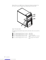
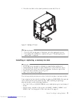
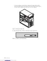
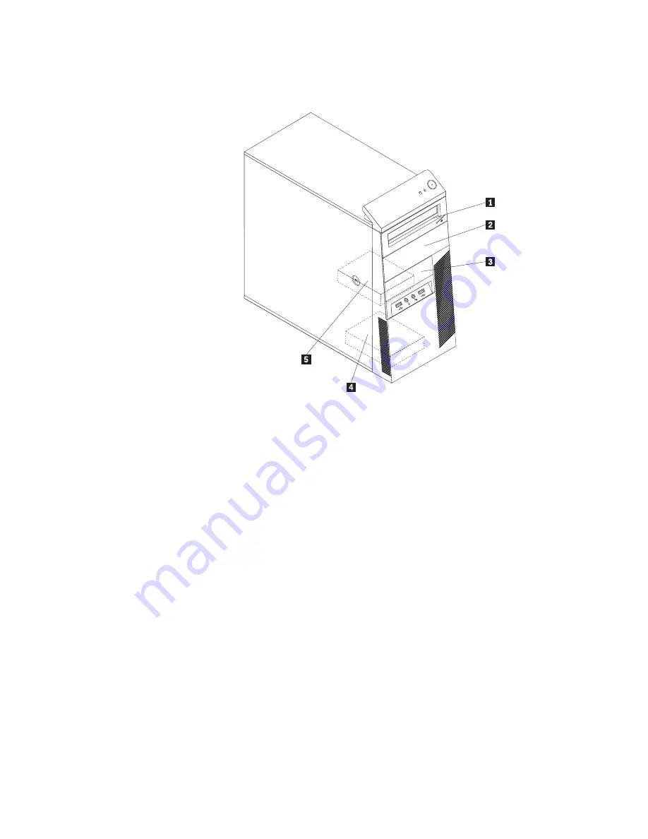
Internal drives are installed in bays. In this manual, the bays are referred to as
bay 1, bay 2, and so on. Figure 5 shows the locations of the drive bays.

The following list describes the type and size of the drive that you can install in
each bay:

1

Bay 1 - Maximum height: 43.0 mm (1.7 inches)

Optical drive

2

Bay 2 - Maximum height: 43.0 mm (1.7 inches)

Optical drive

3

Bay 3 - Maximum height: 25.8 mm (1.0 inch)

3.5-inch card reader

4

Bay 4 - Maximum height: 25.8 mm (1.0 inch)

3.5-inch secondary SATA hard disk
drive

5

Bay 5 - Maximum height: 25.8 mm (1.0 inch)

3.5-inch primary SATA hard disk
drive

Figure 5. Drive bay locations

12

User Guide

Содержание ThinkCentre 3349

Страница 1: ...Machine Types 3029 3054 3139 3219 3246 3282 3349 3421 3544 3652 3769 3934 4992 5206 5267 5325 5384 5450 5474 5498 5554 5852 6232 and 6590 ThinkCentre User Guide ...

Страница 2: ......

Страница 3: ...ThinkCentre User Guide ...

Страница 4: ... have been developed exclusively at private expense and are sold to governmental entities as commercial items as defined by 48 C F R 2 101 with limited and restricted rights to use reproduction and disclosure LIMITED AND RESTRICTED RIGHTS NOTICE If products data computer software or services are delivered pursuant a General Services Administration GSA contract use reproduction or disclosure is sub...

Страница 5: ...ons 51 Performing a backup operation 51 Performing a recovery operation 51 Using the Rescue and Recovery workspace 52 Creating and using a rescue medium 53 Creating a rescue medium 53 Using a rescue medium 54 Installing or reinstalling device drivers 55 Solving recovery problems 55 Chapter 4 Using the Setup Utility program 57 Starting the Setup Utility program 57 Viewing and changing settings 57 U...

Страница 6: ...European conformance CE mark 76 Trademarks 76 Index 77 iv User Guide ...

Страница 7: ...at you received with this product for the latest safety information Reading and understanding this safety information reduces the risk of personal injury and or damage to your product If you no longer have a copy of the ThinkCentre Safety and Warranty Guide you can obtain a Portable Document Format PDF version from the Lenovo Support Web site at http www lenovo com support Copyright Lenovo 2010 v ...

Страница 8: ...vi User Guide ...

Страница 9: ...oprocessor Memory v Supports up to four double data rate 3 dual inline memory modules DDR3 DIMMs Internal drives v Optical drive v Serial Advanced Technology Attachment SATA internal hard disk drive installed in some models Video subsystem v Integrated graphics card for a VGA Video Graphics Array connector and a DisplayPort connector not applicable on some models v PCI Peripheral Component Interco...

Страница 10: ...models v One VGA monitor connector not applicable on some models v One Personal System 2 PS 2 keyboard connector optional v One PS 2 mouse connector optional v Three audio connectors on the rear panel audio line in connector audio line out connector and microphone connector v Two audio connectors on the front panel microphone connector and headphone connector For more information see Locating conn...

Страница 11: ...information see Software overview on page 5 Preinstalled operating system Your computer is preinstalled with one of the following operating systems v Microsoft Windows 7 v Microsoft Windows Vista v Microsoft Windows XP Professional preinstalled through downgrade rights in Windows 7 Professional Operating system s certified or tested for compatibility1 varies by model type v Linux 1 The operating s...

Страница 12: ...h package Non operating 10 to 60 C 14 to 140 F without package Humidity Operating 20 to 80 non condensing Non operating 20 to 90 non condensing Altitude Operating 50 to 10 000 ft 15 2 to 3 048 m Non operating 50 to 35 000 ft 15 2 to 10 668 m Electrical input Input voltage Low range Minimum 100 V ac Maximum 127 V ac Input frequency range 50 to 60 Hz Voltage selection switch setting 115 V ac High ra...

Страница 13: ... operating system from Lenovo Lenovo Welcome The Lenovo Welcome program introduces you to some innovative built in features of Lenovo and guides you through a few important setup tasks to help you make the most of your computer Note The Lenovo Welcome program is only available on computers preinstalled with the Windows 7 operating system or the Windows Vista operating system from Lenovo ThinkVanta...

Страница 14: ...uter improve computing security diagnose computer problems get familiar with the innovative technologies provided by Lenovo and get more information about your computer See Lenovo ThinkVantage Toolbox on page 66 for detailed information PC Doctor for Rescue and Recovery The PC Doctor for Rescue and Recovery diagnostic program is preinstalled on your hard disk drive It is part of the Rescue and Rec...

Страница 15: ...ront of your computer Figure 1 shows the locations of the connectors on the front of your computer 1 USB connector 3 Microphone connector 2 Headphone connector 4 USB connector Figure 1 Front connector locations Chapter 1 Product overview 7 ...

Страница 16: ...h some models 9 Microphone connector 2 Power cord connector 10 Audio line out connector 3 Serial port 11 Audio line in connector 4 PS 2 keyboard and mouse connectors optional 12 PCI Express x16 graphics card slot 5 VGA monitor connector not applicable on some models 13 PCI Express x1 card slot 6 DisplayPort connector not applicable on some models 14 PCI card slots 2 7 USB connectors 6 15 Optional ...

Страница 17: ...a local area network LAN Note To operate the computer within FCC Class B limits use a Category 5 Ethernet cable Microphone connector Used to attach a microphone to your computer when you want to record sound or if you use speech recognition software PS 2 keyboard connector optional Used to attach a keyboard that uses a PS 2 keyboard connector PS 2 mouse connector optional Used to attach a mouse a ...

Страница 18: ... see Removing the computer cover on page 14 1 Heat sink and fan assembly 6 Battery 2 Memory modules 7 Cover presence switch also called intrusion switch 3 Optical drive 8 Rear fan assembly 4 Front audio and USB assembly 9 Power supply assembly 5 PCI card installed in some models Figure 3 Component locations 10 User Guide ...

Страница 19: ...graphics card slot 10 Diskette drive connector 24 System fan connector 11 Parallel connector 25 Cover presence switch connector Intrusion switch connector 12 SATA connectors 3 26 Battery 13 eSATA connector 27 PS 2 keyboard and mouse connector 14 Power fan connector Locating internal drives Internal drives are devices that your computer uses to read and store data You can add drives to your compute...

Страница 20: ...ve that you can install in each bay 1 Bay 1 Maximum height 43 0 mm 1 7 inches Optical drive 2 Bay 2 Maximum height 43 0 mm 1 7 inches Optical drive 3 Bay 3 Maximum height 25 8 mm 1 0 inch 3 5 inch card reader 4 Bay 4 Maximum height 25 8 mm 1 0 inch 3 5 inch secondary SATA hard disk drive 5 Bay 5 Maximum height 25 8 mm 1 0 inch 3 5 inch primary SATA hard disk drive Figure 5 Drive bay locations 12 U...

Страница 21: ...etal surface on the computer for at least two seconds This reduces static electricity in the package and your body v When possible remove the new part from the static protective packaging and install it directly in the computer without setting the part down When this is not possible place the static protective package that the part came in on a smooth level surface and place the part on it v Do no...

Страница 22: ...ty Guide that came with your computer To obtain a copy of the ThinkCentre Safety and Warranty Guide go to http www lenovo com support This section provides instructions on how to remove the computer cover CAUTION Turn off the computer and wait three to five minutes to let the computer cool before removing the computer cover To remove the computer cover do the following 1 Remove any media from the ...

Страница 23: ...ety and Warranty Guide that came with your computer To obtain a copy of the ThinkCentre Safety and Warranty Guide go to http www lenovo com support This section provides instructions on how to remove and reinstall the front bezel To remove and reinstall the front bezel do the following 1 Turn off the computer and disconnect all power cords from electrical outlets 2 Remove the computer cover See Re...

Страница 24: ...ttempt any repair before reading and understanding the Important safety information in the ThinkCentre Safety and Warranty Guide that came with your computer To obtain a copy of the ThinkCentre Safety and Warranty Guide go to http www lenovo com support This section provides instructions on how to install or replace a PCI card Your computer has two standard PCI card slots one PCI Express x1 card s...

Страница 25: ...3 At the rear of the computer press the release button 1 to open the card latch 2 Figure 8 Opening the PCI card latch Chapter 2 Installing or replacing hardware 17 ...

Страница 26: ...lot b If the card is held in place by a retaining latch press the card retaining latch 1 as shown to disengage the latch Grasp the card and then gently pull it out of the slot 5 Remove the new PCI card from its static protective package 6 Install the new card into the appropriate slot on the system board See Locating parts on the system board on page 11 Note If you are installing a PCI Express x16...

Страница 27: ... with your computer To obtain a copy of the ThinkCentre Safety and Warranty Guide go to http www lenovo com support This section provides instructions on how to install or replace a memory module Your computer has four slots for installing or replacing DDR3 DIMMs that provide up to a maximum of 16 GB system memory When installing or replacing a memory module use the following guidelines v Use 1 GB...

Страница 28: ...Remove any parts that might prevent your access to the memory slots Depending on your computer model you might need to remove the PCI Express x16 graphics card for easier access to the memory slots See Installing or replacing a PCI card on page 16 5 Open the retaining clips If you are replacing an old memory module open the retaining clips and gently pull the memory module out of the memory slot F...

Страница 29: ... Guide that came with your computer To obtain a copy of the ThinkCentre Safety and Warranty Guide go to http www lenovo com support This section provides instructions on how to install or replace the optical drive To install or replace an optical drive do the following 1 Turn off the computer and disconnect all power cords from electrical outlets 2 Remove the computer cover See Removing the comput...

Страница 30: ...e rear of the optical drive press the blue release button and then slide the optical drive out of the front of the computer 5 Install the optical drive retainer on the side of the new optical drive Figure 14 Removing the optical drive Figure 15 Installing the optical drive retainer 22 User Guide ...

Страница 31: ...ve 8 Reinstall the front bezel See Removing and reinstalling the front bezel on page 15 What to do next v To work with another piece of hardware go to the appropriate section v To complete the installation or replacement go to Completing the parts replacement on page 43 Figure 16 Installing the optical drive Figure 17 Connecting the optical drive Chapter 2 Installing or replacing hardware 23 ...

Страница 32: ...on information including passwords are lost An error message is displayed when you turn on the computer Refer to the Lithium battery notice in the ThinkCentre Safety and Warranty Guide for information about replacing and disposing of the battery To replace the battery do the following 1 Turn off the computer and disconnect all power cords from electrical outlets 2 Remove the computer cover See Rem...

Страница 33: ... in the ThinkCentre Safety and Warranty Guide that came with your computer To obtain a copy of the ThinkCentre Safety and Warranty Guide go to http www lenovo com support This section provides instructions on how to replace the power supply assembly To replace the power supply assembly do the following 1 Turn off the computer and disconnect all power cords from electrical outlets 2 Remove the comp...

Страница 34: ...00 127 V ac set the switch to 115 V v If the voltage supply range in your local country or region is 200 240 V ac set the switch to 230 V 8 Install the new power supply assembly into the chassis so that the screw holes in the power supply assembly align with those in the chassis 9 Install and tighten the four screws to secure the power supply assembly Note Use only screws provided by Lenovo 10 Rec...

Страница 35: ...n off the computer and wait three to five minutes to let the computer cool before removing the computer cover To replace the heat sink and fan assembly do the following 1 Turn off the computer and disconnect all power cords from electrical outlets 2 Remove the computer cover See Removing the computer cover on page 14 3 Lay the computer on its side for easier access to the system board 4 Locate the...

Страница 36: ... the heat sink and fan assembly 8 Position the new heat sink and fan assembly on the system board so that the four screws are aligned with the holes on the system board Note Position the new heat sink and fan assembly so that the heat sink and fan assembly cable is toward the microprocessor fan connector on the system board 9 Alternate tightening each screw a small and equal amount until the heat ...

Страница 37: ...com support This section provides instructions on how to replace the primary hard disk drive if your computer has one For computer models that do not have an internal hard disk drive and use a remote hard disk drive accessed through the SMC Storage Array contact your network or storage administrator To replace the primary hard disk drive do the following 1 Turn off the computer and disconnect all ...

Страница 38: ... blue bracket to remove the hard disk drive from the bracket 9 To install a new hard disk drive into the blue bracket flex the bracket and align pin 1 pin 2 pin 3 and pin 4 on the bracket with the corresponding holes in the hard disk drive Do not touch the circuit board 5 on the bottom of the hard disk drive 10 Slide the new hard disk drive into the drive cage until it snaps into position Figure 2...

Страница 39: ...n or replacement go to Completing the parts replacement on page 43 Replacing the secondary hard disk drive Attention Do not open your computer or attempt any repair before reading and understanding the Important safety information in the ThinkCentre Safety and Warranty Guide that came with your computer To obtain a copy of the ThinkCentre Safety and Warranty Guide go to http www lenovo com support...

Страница 40: ...ive See Locating internal drives on page 11 4 Disconnect the signal cable and the power cable from the hard disk drive 5 Press the blue release button to release the hard disk drive cage from the chassis 6 Remove the hard disk drive cage from the chassis by simply sliding it outward 7 Pull on the blue handle to release and remove the hard disk drive from the hard disk drive cage 8 Flex the sides o...

Страница 41: ...ive into the hard disk drive cage until it snaps into position 11 Install the hard disk drive cage into the chassis until it snaps into position underneath the metal tab Make sure that the hard disk drive cage release button is secured in the chassis 12 Connect the signal cable and the power cable to the new hard disk drive Figure 26 Installing the hard disk drive into the bracket Figure 27 Instal...

Страница 42: ...e ThinkCentre Safety and Warranty Guide go to http www lenovo com support This section provides instructions on how to replace the front fan assembly Note Not all computers have the front fan assembly To replace the front fan assembly do the following 1 Turn off the computer and disconnect all power cords from electrical outlets 2 Remove the computer cover See Removing the computer cover on page 1...

Страница 43: ...two tabs 1 that attach the front fan assembly to the chassis as shown and then completely remove the front fan from the chassis Figure 28 Removing the front fan assembly Chapter 2 Installing or replacing hardware 35 ...

Страница 44: ...nt fan assembly is secured in place 7 Connect the front fan assembly cable to the power fan connector on the system board What to do next v To work with another piece of hardware go to the appropriate section v To complete the installation or replacement go to Completing the parts replacement on page 43 Figure 29 Installing the front fan assembly 36 User Guide ...

Страница 45: ... the computer cover on page 14 3 Locate the rear fan assembly See Locating components on page 10 4 Disconnect the rear fan assembly cable from the system fan connector on the system board See Locating parts on the system board on page 11 5 The rear fan assembly is attached to the chassis by four rubber mounts Remove the rear fan assembly by breaking or cutting the rubber mounts and gently pulling ...

Страница 46: ... the installation or replacement go to Completing the parts replacement on page 43 Replacing the front audio and USB assembly Attention Do not open your computer or attempt any repair before reading and understanding the Important safety information in the ThinkCentre Safety and Warranty Guide that came with your computer To obtain a copy of the ThinkCentre Safety and Warranty Guide go to http www...

Страница 47: ...11 Note Make sure you note the locations of the cables when you disconnect the cables from the system board 6 Remove the screw that secures the front audio and USB assembly to the chassis 7 Remove the front audio and USB assembly from the chassis 8 Install a new front audio and USB assembly into the chassis and align the screw hole in the front audio and USB assembly with the hole in the chassis 9...

Страница 48: ...uter To obtain a copy of the ThinkCentre Safety and Warranty Guide go to http www lenovo com support This section provides instructions on how to replace the internal speaker Note Not all computers have the internal speaker To replace the internal speaker do the following 1 Turn off the computer and disconnect all power cords from electrical outlets 2 Remove the computer cover See Removing the com...

Страница 49: ... tab 1 on the top of the internal speaker outward and slide the internal speaker upward to completely remove it from the chassis Figure 33 Removing the old internal speaker Chapter 2 Installing or replacing hardware 41 ...

Страница 50: ...he keyboard or mouse Attention Do not open your computer or attempt any repair before reading and understanding the Important safety information in the ThinkCentre Safety and Warranty Guide that came with your computer To obtain a copy of the ThinkCentre Safety and Warranty Guide go to http www lenovo com support This section provides instructions on how to replace the keyboard or mouse To replace...

Страница 51: ...ts you installed or replaced you might need to confirm the updated information in the Setup Utility program Refer to Chapter 4 Using the Setup Utility program on page 57 To reinstall the computer cover and reconnect cables to your computer do the following 1 Make sure that all components have been reassembled correctly and that no tools or loose screws are left inside your computer See Locating co...

Страница 52: ...etup Utility program on page 57 Note In most areas of the world Lenovo requires the return of the defective Customer Replaceable Unit CRU Information about this will come with the CRU or will come a few days after the CRU arrives Obtaining device drivers You can obtain device drivers for operating systems that are not preinstalled at http www lenovo com support Installation instructions are provid...

Страница 53: ...anent fixture The cable lock attaches to the integrated cable lock slot at the rear of your computer and is operated with a key The cable lock also locks the buttons used to remove the computer cover This is the same type of lock used with many notebook computers You can order an integrated cable lock directly from Lenovo by searching for Kensington at http www lenovo com support Figure 37 Integra...

Страница 54: ...gotten passwords such as a user password To erase a lost or forgotten password do the following 1 Turn off the computer and disconnect all power cords from electrical outlets 2 Remove the computer cover See Removing the computer cover on page 14 3 Locate the Clear CMOS Recovery jumper on the system board See Locating parts on the system board on page 11 4 Move the jumper from the standard position...

Страница 55: ...ove the Clear CMOS Recovery jumper back to the standard position pin 1 and pin 2 9 Reinstall the computer cover and connect the power cord See Completing the parts replacement on page 43 Chapter 2 Installing or replacing hardware 47 ...

Страница 56: ...48 User Guide ...

Страница 57: ...use recovery media to restore the hard disk drive to the factory default settings Recovery media are useful if you transfer the computer to another area sell the computer recycle the computer or put the computer in an operational state after all other methods of recovery have failed As a precautionary measure it is important to create recovery media as early as possible Note The recovery operation...

Страница 58: ...Repeatedly press and release the F12 key when turning on the computer When the Please select boot device window opens release the F12 key 3 Select the desired startup device and press Enter The restore process begins 4 Follow the instructions on the screen to complete the operation Notes 1 After restoring your computer to the factory default settings you might have to reinstall device drivers for ...

Страница 59: ...nly the Windows operating system and applications Performing a backup operation This section provides instructions on how to perform a backup operation using the Rescue and Recovery program on different operating systems v To perform a backup operation using the Rescue and Recovery program on the Windows 7 operating system do the following 1 From the Windows desktop click Start All Programs Lenovo...

Страница 60: ...perform recovery operations even if you cannot start the Windows operating system You can perform the following recovery operations from the Rescue and Recovery workspace v Rescue files from your hard disk drive or from a backup The Rescue and Recovery workspace enables you to locate files on your hard disk drive and transfer them to a network drive or other recordable media such as a USB device o...

Страница 61: ...ck Restore your system and follow the instructions on the screen For more information about the features of the Rescue and Recovery workspace click Help Notes 1 After restoring your hard disk drive to the factory default settings you might have to reinstall device drivers for some devices See Installing or reinstalling device drivers on page 55 2 Some computers come with Microsoft Office or Micros...

Страница 62: ... on the screen to create a rescue medium Using a rescue medium This section provides instructions on how to use the rescue medium you have created v If you have created a rescue medium using a disc use the following instructions to use the rescue medium 1 Turn off your computer 2 Repeatedly press and release the F12 key when turning on the computer When the Please select boot device window opens r...

Страница 63: ...Double click the file and follow the instructions on the screen to complete the installation v In the device subfolder look for a README txt file or a file with the txt extension This file might be named after the operating system such as WIN98 txt The TXT file contains information about how to install the device driver Follow the instructions to complete the installation v If the device subfolder...

Страница 64: ...d information about temporarily or permanently changing the startup device sequence For more information about the Setup Utility program see Chapter 4 Using the Setup Utility program on page 57 It is important to create a rescue medium a recovery repair diskette and a set of recovery media as early as possible and store them in a safe place for future use 56 User Guide ...

Страница 65: ...gram might start automatically when POST detects that hardware has been removed or new hardware has been installed in your computer Viewing and changing settings The Setup Utility program menu lists various items about the system configuration To view or change settings start the Setup Utility program See Starting the Setup Utility program Then follow the instructions on the screen When working wi...

Страница 66: ...ssword When an Administrator Password is set you are prompted to type a valid password each time you try to access the Setup Utility program The Setup Utility program cannot be accessed until a valid password is typed in If both the Power On Password and Administrator Password are set you can type either password However you must use your Administrator Password to change any configuration settings...

Страница 67: ...Setup to enable or disable a USB device v Select ATA Drive Setup to enable or disable an internal or external SATA device 4 Select the desired settings and press Enter 5 Press F10 to save and exit the Setup Utility program See Exiting from the Setup Utility program on page 60 Selecting a startup device If your computer does not start up from a device such as the disc diskette or hard disk drive as...

Страница 68: ...layed on the right side of the screen 4 Press F10 to save and exit the Setup Utility program See Exiting from the Setup Utility program Exiting from the Setup Utility program After you finish viewing or changing settings press Esc to return to the Setup Utility program main menu You might have to press Esc several times Then do one of the following v If you want to save the new settings press F10 ...

Страница 69: ... POST and BIOS When updates are released they are available as downloadable files on the Lenovo Web site at http www lenovo com Instructions for using the POST and BIOS updates are available in a TXT file that is included with the update files For most models you can download either an update program to create a system program update disc or an update program that can be run from the operating sys...

Страница 70: ...on the screen after the download begins 5 Follow the printed instructions to download extract and install the update Recovering from a POST BIOS update failure If the power to your computer is interrupted while the POST BIOS is being updated flash update your computer might not restart correctly If this happens perform the following procedure commonly called Boot block Recovery 1 Remove all media ...

Страница 71: ...urns off 10 Repeat step 1 through step 4 11 Move the Clear CMOS Recovery jumper back to the standard position pin 1 and pin 2 12 Reconnect any cables that were disconnected and reinstall the PCI card if removed 13 Reinstall the computer cover and reconnect any cables that were disconnected 14 Turn on the computer to restart the operating system Chapter 5 Updating system programs 63 ...

Страница 72: ...64 User Guide ...

Страница 73: ...t is switched on v The power indicator on the front of the computer is on v The computer voltage matches the voltage available at the electrical outlet for your country or region The monitor screen is blank Verify that v The monitor signal cable is correctly connected to the monitor and to the appropriate monitor connector on the computer v The monitor power cord is correctly connected to the moni...

Страница 74: ... v Lenovo ThinkVantage Toolbox used when you are running the Windows operating system v PC Doctor for Rescue and Recovery used when your Windows operating system does not start Notes 1 You can also download the PC Doctor for DOS diagnostic program from http www lenovo com support See PC Doctor for DOS on page 67 for detailed information 2 If you are unable to isolate and repair the problem yoursel...

Страница 75: ...t you from gaining access to the Rescue and Recovery workspace you can run the PC Doctor for Rescue and Recovery diagnostic program after using a rescue medium to recover the computer from failures and gaining access to the Rescue and Recovery workspace See Creating and using a rescue medium on page 53 PC Doctor for DOS You can also download the latest version of the PC Doctor for DOS diagnostic p...

Страница 76: ... disc from the optical drive when you complete the diagnostic process Cleaning an optical mouse This section provides instructions on how to clean an optical mouse An optical mouse uses a LED and an optical sensor to navigate the pointer If the pointer on the screen does not move smoothly with the optical mouse you might need to clean the mouse To clean an optical mouse do the following 1 Turn off...

Страница 77: ... PDF version To view the publication you need to have the Adobe Reader program preinstalled on your computer If the Adobe Reader program has not been installed on your computer a message will be displayed when you attempt to view the PDF file and you will be guided through the Adobe Reader installation 2 The publication is available in other languages on the Lenovo Support Web site at http www len...

Страница 78: ...lled Windows 7 or Windows Vista operating system and preinstalled software programs from Lenovo Access Help The Access Help information system provides information about getting started doing basic tasks customizing settings for your personal preference protecting data expanding and upgrading and troubleshooting Note The Access Help information system is only available on computers that have an in...

Страница 79: ...dditional resources to help you troubleshoot your computer problem see Information resources on page 69 If you suspect a software problem see the documentation that comes with the operating system or software program including readme files and online help Most computers come with a set of diagnostic programs that help you identify hardware problems For instructions on using the diagnostic programs...

Страница 80: ...nd software configuration information Using other services If you travel with your computer or relocate it to a country where your desktop or notebook computer machine type is sold your computer might be eligible for International Warranty Service which automatically entitles you to obtain warranty service throughout the warranty period Service will be performed by service providers authorized to ...

Страница 81: ...systems and application programs network setup and configuration upgraded or extended hardware repair services and custom installations Service availability and service name might vary by country or region For more information about these services go to the Lenovo Web site at http www lenovo com Chapter 7 Getting information help and service 73 ...

Страница 82: ...74 User Guide ...

Страница 83: ...information could include technical inaccuracies or typographical errors Changes are periodically made to the information herein these changes will be incorporated in new editions of the publication Lenovo may make improvements and or changes in the product s and or the program s described in this publication at any time without notice The products described in this document are not intended for u...

Страница 84: ...n and other rights owners Use of this copyright protection technology must be authorized by Macrovision Corporation and is intended for home and other limited viewing uses only unless otherwise authorized by Macrovision Corporation Reverse engineering or disassembly is prohibited European conformance CE mark Trademarks The following terms are trademarks of Lenovo in the United States other countri...

Страница 85: ... 13 diagnostics programs using 71 diagnostics troubleshooting 65 DisplayPort connector 9 documentation using 71 drivers device 44 drives bays 11 specifications 11 E environment operating 4 Ethernet 1 Ethernet connector 9 exiting Setup Utility 60 expansion 2 external options installing 14 F failure recovering from POST BIOS 62 features 1 flashing the BIOS 61 folder books online 69 front audio and U...

Страница 86: ... programs updating system 61 protection password 46 purchasing additional services 73 R rear connectors 8 rear fan assembly replacing 37 recovering from a POST BIOS update failure 62 software 49 recovery boot block 62 operations backup and 51 problems solving 55 recovery media creating and using 49 reinstalling device drivers 55 removing computer cover 14 replacing battery 24 hard disk drive 29 he...

Страница 87: ...ing basic 65 troubleshooting diagnostics 65 U updating flashing the BIOS 61 system programs 61 updating flashing the BIOS 62 USB connector 9 using a rescue medium creating and 53 diagnostic programs 71 documentation 71 other services 72 passwords 57 Setup Utility 57 V VGA monitor connector 9 video subsystem 1 viewing and changing settings 57 W warranty information 70 Web site Lenovo 71 workspace b...

Страница 88: ...80 User Guide ...

Страница 89: ......

Страница 90: ...Part Number 71Y7146 Printed in USA 1P P N 71Y7146 ...

Отзывы: