42
Lenovo ideapad 2in1 14 Hardware Maintenance Manual
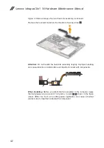
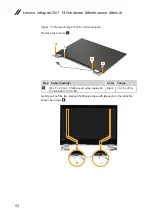
Figure 8. Removal steps of fan and heat sink assembly (continued)
Remove the heat sink module in the direction shown by arrow
2
.
2
Attention:
Do not handle the heat sink assembly roughly. Improper handling
can cause distortion or deformation and imperfect contact with components.
a
b
When installing:
Before you attach the fan assembly to the computer, apply
thermal grease, at an amount of 0.2 grams, to parts
a
b
shown in the figure
above. Either too much or too little grease application can cause a thermal
problem due to imperfect contact with a component.
Содержание IdeaPad 2 in 1-14
Страница 1: ...Lenovo ideapad 2in1 14 Hardware Maintenance Manual ...
Страница 57: ...53 Lenovo ideapad 2in1 14 Figure 13 Removal steps of LCD unit continued Lift the LCD unit 5 5 5 ...
Страница 68: ...64 Lenovo ideapad 2in1 14 Hardware Maintenance Manual Rear view a Ventilation slots 1 ...
Страница 70: ...66 Lenovo ideapad 2in1 14 Hardware Maintenance Manual Overall 1 e 4 5 7 9 10 a b 12 14 d 2 3 6 8 11 c 13 ...
Страница 85: ...81 Lenovo ideapad 2in1 14 Region P N CRU ID Table 10 Parts list 3 pin power cords continued ...


