Lenovo IdeaCentre A520 Скачать руководство пользователя страница 43

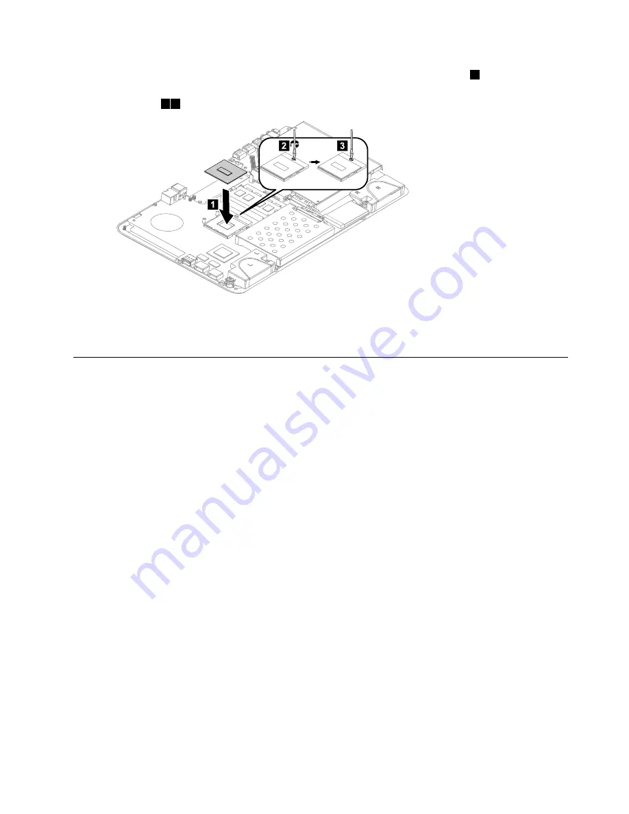
Step 11. Lower the microprocessor straight down into its socket on the motherboard.

1

Step 12. To secure the microprocessor by turning the CPU lock screw clockwise to lock the CPU into

position.

2 3

2

3

1

Step 13. Use a thermal grease syringe to place 5 drops of grease on the top of the microprocessor. Each

drop of grease should be 0.03 ml (3 tick marks on the grease syringe).

Step 14. Reattach the system fan, heat-sink, and base cover, then secure them with the screws.

Replacing the optical drive

Attention:

Turn off the computer and wait 3 to 5 minutes to let it cool down before removing the base cover.

To replace the optical drive:

Step 1.

Remove any media (disks, CDs, DVDs, or memory cards) from the drives, shut down the operating
system, and turn off the computer and all attached devices.

Step 2.

Unplug all power cords from electrical outlets.

Step 3.

Disconnect all cables attached to the computer. This includes power cords, input/output (I/O)
cables, and any other cables that are connected to the computer. Refer to “Left and right view”
and “Rear view” for help with locating the various connectors.

Step 4.

Remove the base cover. Refer to “Removing the base cover”.

Step 5.

Disconnect the optical drive data cable from the connector on the motherboard.

Chapter 8

.

Replacing hardware

37

Содержание IdeaCentre A520

Страница 1: ...IdeaCentre A520 All In One PC Hardware Maintenance Manual ideaideaideaCentreidea Machine Types 6597 10106 A520 ...

Страница 2: ......

Страница 3: ...IdeaCentre A520 All In One PC Hardware Maintenance Manual Machine Types 6597 10106 A520 ...

Страница 4: ...ght Lenovo 2012 LIMITED AND RESTRICTED RIGHTS NOTICE If data or software are delivered pursuant a General Services Administration GSA contract use reproduction or disclosure is subject to restrictions set forth in Contract No GS 35F 05925 ...

Страница 5: ... controls and components 21 Chapter 8 Replacing hardware 27 General information 27 Replacing the keyboard and mouse 28 Replacing the power adapter 28 Removing the base cover 30 Replacing the hard disk drive 31 Replacing a memory module 32 Replacing the system fan 33 Replacing the heat sink 34 Replacing the CPU 35 Replacing the optical drive 37 Replacing the solid state disk 39 Replacing the mother...

Страница 6: ...iv IdeaCentre A520 All In One PCHardware Maintenance Manual ...

Страница 7: ...TION and DANGER sections in this manual before following any of the instructions Veuillez lire toutes les consignes de type DANGER et ATTENTION du présent document avant d exécuter les instructions Lesen Sie unbedingt alle Hinweise vom Typ ACHTUNG oder VORSICHT in dieser Dokumentation bevor Sie irgendwelche Vorgänge durchführen Leggere le istruzioni introdotte da ATTENZIONE e PERICOLO presenti nel...

Страница 8: ...2 IdeaCentre A520 All In One PCHardware Maintenance Manual ...

Страница 9: ... from areas that people may walk through to ensure no one trips over it Do not wear loose clothing that can be trapped in the moving parts of a machine Ensure that your sleeves are fastened or rolled up above your elbows If your hair is long tie or fasten it back Insert the ends of your necktie or scarf inside clothing or fasten it with a nonconductive clip approximately 8 centimeters 3 inches fro...

Страница 10: ...t be a complete circuit to cause electrical shock By observing the above rule you may prevent a current from passing through your body When using a tester set the controls correctly and use the approved probe leads and accessories for that tester Stand on suitable rubber mats obtained locally if necessary to insulate you from grounds such as metal floor strips and machine frames Observe the specia...

Страница 11: ...connect the power cord 3 Check the power cord for a A third wire ground connector in good condition Use a meter to measure third wire ground continuity for 0 1 ohm or less between the external ground pin and frame ground b The power cord should be the appropriate type as specified in the parts listings c Insulation must not be frayed or worn 4 Remove the cover 5 Check for any obvious alterations U...

Страница 12: ...cal grounding of the computer is required for operator safety and correct system function Proper grounding of the electrical outlet can be verified by a certified electrician Safety notices The CAUTION and DANGER safety notices in this section are provided in the language of English DANGER Electrical current from power telephone and communication cables is hazardous To avoid a shock hazard Do not ...

Страница 13: ...row into or immerse in water Heat to more than 100 C 212 F Repair or disassemble Dispose of the battery as required by local ordinances or regulations CAUTION When laser products such as CD ROMs DVD ROM drives fiber optic devices or transmitters are installed note the following Do not remove the covers Removing the covers of the laser product could result in exposure to hazardous laser radiation T...

Страница 14: ...turn off the electrical current supplied to the device The device also might have more than one power cord To remove all electrical current from the device ensure that all power cords are disconnected from the power source 1 2 CAUTION Do not place any object weighing more than 82 kg 180 lbs on top of rack mounted devices 8 IdeaCentre A520 All In One PCHardware Maintenance Manual ...

Страница 15: ...ons for your computer This section lists the physical specifications for your computer Type IdeaCentre A520 This section lists the physical specifications Environment Air temperature Operating 10 to 35 C Transit 20 to 55 C Humidity Operating 35 to 80 Transit 20 to 90 40 C Altitude 86KPa to 106KPa Electrical input Input voltage 90V 264V AC Input frequency 47Hz 63Hz Copyright Lenovo 2012 9 ...

Страница 16: ...10 IdeaCentre A520 All In One PCHardware Maintenance Manual ...

Страница 17: ...cedure to help determine the cause of the problem 1 Power off the computer and all external devices 2 Check all cables and power cords 3 Set all display controls to the middle position 4 Power on all external devices 5 Power on the computer Look for displayed error codes Look for readable instructions or a main menu on the display If you did not receive the correct response proceed to step 6 If yo...

Страница 18: ...12 IdeaCentre A520 All In One PCHardware Maintenance Manual ...

Страница 19: ...ee Starting the Setup Utility program You must use the keyboard when using the Lenovo BIOS Setup Utility menu The keys used to perform various tasks are displayed on the bottom of each screen Using passwords You can use the Lenovo BIOS Setup Utility program to set passwords to prevent unauthorized persons from gaining access to your computer and data See Starting the Setup Utility program The foll...

Страница 20: ... To change an Administrator Password do the following 1 Start the Lenovo BIOS Setup Utility program see Starting the Lenovo BIOS Setup Utility program on page 13 2 From the Security menu select Set Administrator Password and press the Enter key 3 The password dialog box will be displayed Type the current password then press the Enter key 4 Type the new password then press the Enter key Re type the...

Страница 21: ...ter key Re type the new password to confirm it If you typed the new password correctly the new password will be installed A Setup Notice will be displayed confirming that your changes have been saved 5 Return to the Lenovo BIOS Setup Utility program menu and select the Exit option 6 Select Save Changes and Exit from the menu To delete a previously set Power On Password do the following 1 Start the...

Страница 22: ...Exit option 6 Select Save Changes and Exit from the menu Notes a If you do not want to save the settings select Discard Changes and Exit from the menu b Select IDE AHCI Mode Device driver support is required for AHCI Depending on how the hard disk image was installed changing this setting may prevent the system from booting Selecting a startup device If your computer does not boot from a device su...

Страница 23: ...do not want to save the settings select Discard Changes and Exit from the menu b If you have changed these settings and want to return to the default settings select Load Optimal Defaults from the menu Exiting the Lenovo BIOS Setup Utility program After you finish viewing or changing settings press the Esc key to return to the Lenovo BIOS Setup Utility program main menu You might have to press the...

Страница 24: ...18 IdeaCentre A520 All In One PCHardware Maintenance Manual ...

Страница 25: ...d disk drive boot error A hard disk drive boot error can have the following causes Error FRU Action The startup drive is not included in the boot sequence configuration Check the configuration and ensure the startup drive is in the boot sequence No operating system is installed on the boot drive Install an operating system on the boot drive The boot sector on the startup drive is corrupted The dri...

Страница 26: ...p and set the option to Enabled The BIOS then ignores the missing keyboard during POST Reboot and Select proper Boot device or Insert Boot Media in selected Boot device The BIOS was unable to find a suitable boot device Make sure the boot drive is properly connected to the computer Make sure you have bootable media in the boot device Undetermined problems 1 Power off the computer 2 Remove or disco...

Страница 27: ...ny air vents on the computer Blocked air vents can cause overheating 1 2 3 4 8 7 6 5 9 10 11 13 12 14 15 16 17 1 Built in microphone 10 PC mode HDMI in AV in switch 2 Built in camera 11 Novo Vision button 3 Built in microphone selected models only 12 Volume down 4 Power indicator 13 Volume up 5 Hard disk drive indicator 14 Brightness down 6 Bluetooth status indicator 15 Brightness up 7 Wi Fi statu...

Страница 28: ... of the computer 2 3 4 5 6 7 1 8 1 Air vents 5 Optical drive eject button 2 USB 3 0 connector 6 Optical drive 3 HDMI in connector selected models only 7 Power button 4 HDMI out connector 8 Anti scratch protector Attention Do not insert 3 inch discs into the optical drive 22 IdeaCentre A520 All In One PCHardware Maintenance Manual ...

Страница 29: ...e rear of the computer 1 2 3 8 7 6 4 5 1 TV tuner connector selected models only 5 USB 2 0 connectors 2 2 Headphone connector 6 Power connector 3 Microphone connector 7 Ethernet connector RJ45 4 USB 3 0 connector 8 Security cable slot Chapter 7 Locating connectors controls and components 23 ...

Страница 30: ...drive bracket 18 Front function board 4 Hard disk drive 19 Battery 5 Hard disk drive rubbers 20 Solid state disk 6 CPU 21 TV tuner card 7 Base cover 22 Glass 8 Optical drive 23 Panel frame 9 Optical drive bracket 24 LED panel 10 Motherboard 25 Middle frame 11 Chassis 26 Rear cover 12 Speakers 27 Rear cover deco 13 Hinge 28 Touch control board 14 Camera 29 Converter 15 Wi Fi card 30 Heat sink 24 Id...

Страница 31: ...motherboard 1 HDMI out connector 12 TV jack 2 Japan only 2 HDMI in connector 13 Card reader 3 USB 3 0 connector 14 Microphone connector 4 Ethernet connector RJ45 15 Headphone connector 5 Power connector 16 Optical drive eject button connector 6 System fan connector 17 Speaker connector 7 Scalar cable connector 18 Optical drive connector 8 Scalar cable connector 19 Solid state disk connector 9 USB ...

Страница 32: ...he following illustration shows the location of connectors and components on the back of the motherboard 23 TV Tuner card connector 24 Battery 26 IdeaCentre A520 All In One PCHardware Maintenance Manual ...

Страница 33: ...of the Safety and Warranty Guide go to the Support Web site at http support lenovo com Note Use only parts provided by Lenovo General information Pre disassembly instructions Before starting the disassembly procedure make sure that you do the following 1 Turn off the power to the system and all peripherals 2 Unplug all power and signal cables from the computer 3 Place the system on a flat stable s...

Страница 34: ...d Rear view for help with locating the various connectors Note Your keyboard will be connected to a USB connector on one side or at the rear of the computer Step 4 Disconnect the defective keyboard cable from the computer and connect the new keyboard cable to the same connector Note The mouse can be replaced using the same method Replacing the power adapter To replace the power adapter Step 1 Remo...

Страница 35: ...Step 3 Disconnect the failing power adapter from the computer Step 4 To install the new power adapter a Connect the new power adapter to the same connector Chapter 8 Replacing hardware 29 ...

Страница 36: ...he operating system and turn off the computer and all attached devices Step 2 Unplug all power cords from electrical outlets Step 3 Disconnect all cables attached to the computer This includes power cords input output I O cables and any other cables that are connected to the computer Refer to Left and right view and Rear view for help with locating the various connectors Step 4 Place the computer ...

Страница 37: ...DVDs or memory cards from the drives shut down the operating system and turn off the computer and all attached devices Step 2 Unplug all power cords from electrical outlets Step 3 Disconnect all cables attached to the computer This includes power cords input output I O cables and any other cables that are connected to the computer Refer to Left and right view and Rear view for help with locating t...

Страница 38: ...g a memory module Attention Turn off the computer and wait 3 to 5 minutes to let it cool down before removing the base cover To replace a memory module Step 1 Remove any media disks CDs DVDs or memory cards from the drives shut down the operating system and turn off the computer and all attached devices Step 2 Unplug all power cords from electrical outlets Step 3 Disconnect all cables attached to ...

Страница 39: ...omputer and wait 3 to 5 minutes to let it cool down before removing the base cover To replace the system fan Step 1 Remove any media disks CDs DVDs or memory cards from the drives shut down the operating system and turn off the computer and all attached devices Step 2 Unplug all power cords from electrical outlets Step 3 Disconnect all cables attached to the computer This includes power cords inpu...

Страница 40: ...mputer and wait 3 to 5 minutes to let it cool down before removing the base cover To replace the heat sink Step 1 Remove any media disks CDs DVDs or memory cards from the drives shut down the operating system and turn off the computer and all attached devices Step 2 Unplug all power cords from electrical outlets Step 3 Disconnect all cables attached to the computer This includes power cords input ...

Страница 41: ...ing the CPU Note Turn off the computer and wait 3 to 5 minutes to let it cool down before removing the base cover To replace the CPU Step 1 Remove any media disks CDs DVDs or memory cards from the drives shut down the operating system and turn off the computer and all attached devices Step 2 Unplug all power cords from electrical outlets Step 3 Disconnect all cables attached to the computer This i...

Страница 42: ...e socket pins must be kept as clean as possible Step 9 Holding the sides of the microprocessor with your fingers remove the protective cover 1 that protects the gold contacts on the new microprocessor 2 Step 10 Holding the sides of the microprocessor with your fingers position the microprocessor so that the notches on the microprocessor are aligned with the tabs in the microprocessor socket Import...

Страница 43: ... 3 to 5 minutes to let it cool down before removing the base cover To replace the optical drive Step 1 Remove any media disks CDs DVDs or memory cards from the drives shut down the operating system and turn off the computer and all attached devices Step 2 Unplug all power cords from electrical outlets Step 3 Disconnect all cables attached to the computer This includes power cords input output I O ...

Страница 44: ...to the motherboard and lift the optical drive up to remove it Step 7 Remove the 4 screws that secure the optical drive to the bracket and disconnect the data connector from the rear of optical drive 38 IdeaCentre A520 All In One PCHardware Maintenance Manual ...

Страница 45: ...o the connector on the motherboard Step 11 Reattach the base cover and secure it with the screws Replacing the solid state disk Note Turn off the computer and wait 3 to 5 minutes to let it cool down before removing the base cover To replace the solid state disk Step 1 Remove any media disks CDs DVDs or memory cards from the drives shut down the operating system and turn off the computer and all at...

Страница 46: ...Disconnect all cables attached to the computer This includes power cords input output I O cables and any other cables that are connected to the computer Refer to Left and right view and Rear view for help with locating the various connectors Step 4 Remove the base cover Refer to Removing the base cover Step 5 Remove the hard disk drive Refer to Replacing the hard disk drive Step 6 Remove all memor...

Страница 47: ...is and slide it out as shown Step 15 Remove the 2 screws that secure the TV Tuner card to the motherboard Step 16 Disconnect the antenna cable s from the TV Tuner card Step 17 Pull the TV Tuner card upward to remove it from the card port Chapter 8 Replacing hardware 41 ...

Страница 48: ...na cable s to the TV Tuner card d Line up the new motherboard with the chassis and slide it into position Align the holes on the new motherboard with the mounting holes on the chassis and secure it to the chassis with the screws e Attach the speakers to the chassis with the screws f Attach the solid state disk optical drive CPU heat sink system fan memory module and hard disk drive to the new moth...

Страница 49: ...puter Refer to Left and right view and Rear view for help with locating the various connectors Step 4 Remove the base cover Refer to Removing the base cover Step 5 Remove the hard disk drive Refer to Replacing the hard disk drive Step 6 Remove the optical drive Refer to Replacing the optical drive Step 7 Remove the system fan Refer to Replacing the system fan Step 8 Remove the heat sink Refer to R...

Страница 50: ...V tuner card Step 1 Remove any media disks CDs DVDs or memory cards from the drives shut down the operating system and turn off the computer and all attached devices Step 2 Unplug all power cords from electrical outlets Step 3 Disconnect all cables attached to the computer This includes power cords input output I O cables and any other cables that are connected to the computer Refer to Left and ri...

Страница 51: ...he card port b Secure the new TV Tuner card to the motherboard with the 2 screws c Connect the antenna cable s to the new TV Tuner card Step 16 Line up the motherboard with the chassis and slide it into position Align the holes on the motherboard with the mounting holes on the chassis and secure the motherboard to the chassis with the 7 screws Step 17 Reattach the speaker system optical drive heat...

Страница 52: ...nd right view and Rear view for help with locating the various connectors Step 4 Remove the base cover Refer to Removing the base cover Step 5 Remove the hard disk drive Refer to Replacing the hard disk drive Step 6 Remove the optical drive Refer to Replacing the optical drive Step 7 Remove the system fan Refer to Replacing the system fan Step 8 Remove the heat sink Refer to Replacing the heat sin...

Страница 53: ...5 Reattach the speaker system optical drive heat sink system fan and hard disk drive to the motherboard Step 16 Reconnect all the cables to the motherboard Step 17 Reattach the base cover and secure it with the screws Removing the hinge from the chassis Note Turn off the computer and wait 3 to 5 minutes to let it cool down before removing the base cover To remove the hinge from the chassis Step 1 ...

Страница 54: ...lar and DVI HDMI cables from the connectors on the motherboard Step 6 Remove the 6 screws that secure the hinge to the chassis 1 then lift up the hinge to remove it from the chassis 2 1 2 Step 7 To reattach the hinge to the chassis a Line up the hinge with the chassis and slide the hinge into position b Secure the hinge to the chassis with the 6 screws c Reconnect the scalar headphone input scalar...

Страница 55: ...ious connectors Step 4 Remove the base cover Refer to Removing the base cover Step 5 Remove the hinge from the chassis Refer to Removing the hinge from the chassis Step 6 Raise the hinge 1 and slide the rear deco out as shown 2 1 2 Step 7 Put the head of a flat head screwdriver between the middle frame and the rear cover as shown Then using the screwdriver as a lever and the middle frame metal bar...

Страница 56: ...nnect all cables attached to the computer This includes power cords input output I O cables and any other cables that are connected to the computer Refer to Left and right view and Rear view for help with locating the various connectors Step 4 Remove the base cover Refer to Removing the base cover Step 5 Remove the hinge from the chassis Refer to Removing the hinge from the chassis Step 6 Remove t...

Страница 57: ...isconnect all cables attached to the computer This includes power cords input output I O cables and any other cables that are connected to the computer Refer to Left and right view and Rear view for help with locating the various connectors Step 4 Remove the base cover Refer to Removing the base cover Step 5 Remove the hinge from the chassis Refer to Removing the hinge from the chassis Step 6 Remo...

Страница 58: ... system and turn off the computer and all attached devices Step 2 Unplug all power cords from electrical outlets Step 3 Disconnect all cables attached to the computer This includes power cords input output I O cables and any other cables that are connected to the computer Refer to Left and right view and Rear view for help with locating the various connectors Step 4 Remove the base cover Refer to ...

Страница 59: ...cards from the drives shut down the operating system and turn off the computer and all attached devices Step 2 Unplug all power cords from electrical outlets Step 3 Disconnect all cables attached to the computer This includes power cords input output I O cables and any other cables that are connected to the computer Refer to Left and right view and Rear view for help with locating the various conn...

Страница 60: ... cords from electrical outlets Step 3 Disconnect all cables attached to the computer This includes power cords input output I O cables and any other cables that are connected to the computer Refer to Left and right view and Rear view for help with locating the various connectors Step 4 Remove the base cover Refer to Removing the base cover Step 5 Remove the hinge from the chassis Refer to Removing...

Страница 61: ...ear view for help with locating the various connectors Step 4 Remove the base cover Refer to Removing the base cover Step 5 Remove the hinge from the chassis Refer to Removing the hinge from the chassis Step 6 Remove the rear cover Refer to Removing the rear cover Step 7 Use a small flat head screwdriver to prise the Wi Fi card away from the socket 1 2 Step 8 Disconnect the antenna cable 3 and dat...

Страница 62: ... Refer to Removing the hinge from the chassis Step 6 Remove the rear cover Refer to Removing the rear cover Step 7 Remove the 2 screws that secure the camera to the front bezel 1 Step 8 Lift up the camera 2 and disconnect the data cable from the camera 3 1 2 3 1 Step 9 To install the new camera a Connect the data cable to the new camera b Line up the holes in the new camera with the mounting holes...

Страница 63: ...ng the rear cover Step 7 Remove the 2 screws that secure the front function board to the front bezel 1 Step 8 Disconnect the data cable from the front function board 2 Step 9 Lift up the front function board to remove it from the front bezel 3 3 1 2 1 Step 10 To install the new front function board a Connect the data cable to the new front function board b Line up the holes in the new front functi...

Страница 64: ...tep 4 Remove the base cover Refer to Removing the base cover Step 5 Remove the hinge from the chassis Refer to Removing the hinge from the chassis Step 6 Remove the rear cover Refer to Removing the rear cover Step 7 Remove the scalar board Refer to Replacing the scalar board Step 8 Remove the touch control board Refer to Replacing the touch control board Step 9 Remove the converter board Refer to ...

Страница 65: ...t all the cables to the new LED panel Step 19 Reattach the rear cover to the LED panel Step 20 Reattach the hinge to the chassis Step 21 Reconnect the scalar headphone input scalar and DVI HDMI cables to the motherboard Step 22 Reattach the base cover and secure it with the screws FRU lists This chapter lists the information on the field replaceable units FRUs Attention Be sure to read and underst...

Страница 66: ... 1G_GPU W O HDMI W O TV MB 90001187 N A520 WIN8 2G_GPU W HDMI W TV MB 90001188 N A520 WIN8 2G_GPU W HDMI W O TV MB 90001189 N A520 WIN8 2G_GPU W O HDMI W TV MB 90001190 N 10 Motherboard A520 WIN8 2G_GPU W O HDMI W O TV MB 90001191 N A520 Coolermaster DIS 45W Heat Sink 90201509 N A520 Coolermaster UMA 45W Heat Sink 90201510 N A520 AVC DIS 45W Heat Sink 90201511 N 30 Heat sink A520 AVC UMA 45W Heat ...

Страница 67: ...2019 N A520 WLAN Data Cable 90202020 N A520 Scalar Board Cable 90202021 N A720 TV Tunner Cable For NTSL 90201142 N A720 TV Tunner Cable For PAL 90201143 N Cables A520 Wlan Anntena 90202022 N 12 Speakers A720 Speaker L R 90200743 N 13 Hinge A520 STAND 90202023 N 26 Rear cover A520 Rear Cover 90202024 N 9 ODD bracket A520 ODD Frame 90202025 N 11 Chassis A520 Base Bottom 90202026 N Front function boa...

Страница 68: ...TF25664HZ 1G6M1 1100228 N Elp_R J2108BDBG GN F 2GB D3 1600SMemory 1100425 N M471B5773CHS CK0 2GB D3 1600SMemory HF 1100614 N 2GB PC3 12800 1600MHz DDR3 SODIMM Mic_S D9PFJ 2GB D3 1600SMemory SM322NQ08IBF 1100646 N M471B5273DH0 CK0 1100230 N HMT351S6CFR8C PB 1100231 N MT16KTF51264HZ 1G6M1 1100232 N Elp_R J2108BDBG GN F 4GB D3 1600SMemory 1100426 N M471B5273CH0 CK0 4GB D3 1600SMemory HF 1100613 N 4GB...

Страница 69: ...l LH 25201106 N PLDS DS 8A8SH Slim Rambo ODD LH 25201487 N HLDS GT80N Slim SATA Rambo ODD W O Bezel LH 25209015 N PLDS DS 8A9SH Slim Tray Rambo W O Bezel LH 25209016 N ODD Tray in DVD Rambo TSST SN 208DB Slim Rambo ODD W O Bezel LH 25209014 N PLDS DS 6E2SH BDCombo W O Bezel LH BE 25200328 N HLDS CT40N Slim BD Combo W O Bezel LH 25201493 N Optiarc BC 5550H BD Combo W O Bezel LH 25204159 N 8 ODD Tra...

Страница 70: ...l Black Single end 1 0m India Power Cable 31035395 1 Longwell Black Single end 1 0m Italy C5 Power Cable 31039104 1 Volex 1 0m C5 ItalyPower Cable 31049504 1 Longwell Black Single end 1 0m Brazil Power Cable 31035828 1 Volex 1 0m C5 BrazilPower Cable 31049505 1 Longwell Black Single end 1 0m Argentina C5Power Cable 31039100 1 Volex 1 0m C5 US Power Cable 31049507 1 Longwell Black Single end 1 0m D...

Страница 71: ... N Liteon SM 8861 WW Mouse Silver 25203606 1 Liteon SM 8861 Mouse MY Silver 25203608 1 Liteon SM 8861 Mouse No Battery Silver 25203607 1 Liteon SM 8861 JP Mouse Silver 25205774 1 Liteon N70 2 4G mouse D for Silver Silk 25209297 1 Mouse Liteon N70 2 4G mouse D for S Silk JP 25210202 1 Liteon SK 8861 GB 2 4G KB only Silver8 25209294 1 Liteon SK 8861 FR 2 4G KB only Silver8 25209295 1 Liteon SK 8861 ...

Страница 72: ...lver WW 90200553 1 Liteon SK 8861 JP S Silk KB Silver WW 90200554 1 Liteon SK 8861 US IN S SilkKB Silver WW 90200555 1 Liteon SK 8861 SA S Silk KB Silver WW 90200556 1 Liteon SK 8861 BR S Silk KB Silver WW 90200557 1 Liteon SK 8861 CS SK S SilkKB Silver WW 90200558 1 Liteon SK 8861 GR S Silk KB Silver WW 90200559 1 Liteon SK 8861 KR S Silk KB Silver WW 90200560 1 Liteon SK 8861 LA S Silk KB Silver...

Страница 73: ... As this computer has an ACPI BIOS system the operating system is allowed to control the power management features of the computer and the settings for Advanced Power Management APM BIOS mode is ignored Not all operating systems support ACPI BIOS mode Automatic Power On features The Automatic Power On features within the Power Management menu allow you to enable and disable features that turn on t...

Отзывы: