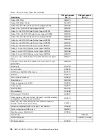
For additional information about tools for updating, managing, and deploying firmware, see the
ToolsCenter for System x and BladeCenter at http://publib.boulder.ibm.com/infocenter/toolsctr/v1r0/.
• Before you install optional hardware, make sure that the server is working correctly. Start the server, and
make sure that the operating system starts, if an operating system is installed, or that a 19990305 error
code is displayed, indicating that an operating system was not found but the server is otherwise working
correctly. If the server is not working correctly, see “Running the DSA Preboot diagnostic programs” on
page 62 for information about how to run diagnostics.
• Observe good housekeeping in the area where you are working. Place removed covers and other parts
in a safe place.
• Do not attempt to lift an object that you think is too heavy for you. If you have to lift a heavy object,
observe the following precautions:
– Make sure that you can stand safely without slipping.
– Distribute the weight of the object equally between your feet.
– Use a slow lifting force. Never move suddenly or twist when you lift a heavy object.
– To avoid straining the muscles in your back, lift by standing or by pushing up with your leg muscles.
• Make sure that you have an adequate number of properly grounded electrical outlets for the server,
monitor, and other devices.
• Back up all important data before you make changes to disk drives.
• Have a small flat-blade screwdriver, a small Phillips screwdriver, and a T8 torx screwdriver available.
• To view the error LEDs on the system board and internal components, leave the server connected to
power.
• You do not have to turn off the server to remove or replace hot-swap power supplies, hot-swap fans, or
hot-plug USB devices. However, you must turn off the server before you perform any steps that involve
removing or installing adapter cables and you must disconnect the power source from the server before
you perform any steps that involve removing or installing a riser card.
• Blue on a component indicates touch points, where you can grip the component to remove it from or
install it in the server, open or close a latch, and so on.
• Orange on a component or an orange label on or near a component indicates that the component can be
hot-swapped, which means that if the server and operating system support hot-swap capability, you can
remove or install the component while the server is running. (Orange can also indicate touch points on
hot-swap components.) See the instructions for removing or installing a specific hot-swap component for
any additional procedures that you might have to perform before you remove or install the component.
• When you are finished working on the server, reinstall all safety shields, guards, labels, and ground wires.
System reliability guidelines
The system reliability guidelines to ensure proper system cooling.
To help ensure proper system cooling and system reliability, make sure that the following requirements
are met:
• Each of the drive bays has a drive or a filler panel and electromagnetic compatibility (EMC) shield
installed in it.
• Each of the power-supply bays has a power supply or a filler installed in it.
• If the server has redundant power, each of the power-supply bays has a power supply installed in it.
• There is adequate space around the server to allow the server cooling system to work properly. Leave
approximately 50 mm (2.0 in.) of open space around the front and rear of the server. Do not place
objects in front of the fans. For proper cooling and airflow, replace the server cover before you turn on
102
HX3510-G, HX5510, HX5510-C, HX7510 Installation and Service Guide
Содержание HX3510-G
Страница 1: ...HX3510 G HX5510 HX5510 C HX7510 Installation and Service Guide Machine Type 8695 ...
Страница 6: ...iv HX3510 G HX5510 HX5510 C HX7510 Installation and Service Guide ...
Страница 62: ...50 HX3510 G HX5510 HX5510 C HX7510 Installation and Service Guide ...
Страница 102: ...90 HX3510 G HX5510 HX5510 C HX7510 Installation and Service Guide ...
Страница 112: ...100 HX3510 G HX5510 HX5510 C HX7510 Installation and Service Guide ...
Страница 1222: ...1210 HX3510 G HX5510 HX5510 C HX7510 Installation and Service Guide ...
Страница 1229: ...People s Republic of China Class A electronic emission statement Taiwan Class A compliance statement Appendix E Notices 1217 ...
Страница 1230: ...Taiwan BSMI RoHS declaration 1218 HX3510 G HX5510 HX5510 C HX7510 Installation and Service Guide ...
Страница 1238: ...1226 HX3510 G HX5510 HX5510 C HX7510 Installation and Service Guide ...
Страница 1239: ......
Страница 1240: ......


