Lenovo HORIZON 2s Скачать руководство пользователя страница 43

Replacing the speaker system

Note:

Turn off the computer and wait 3 to 5 minutes to let it cool down before removing the rear cover.

To replace the speaker system:

Step 1.

Remove any media (disks, CDs, DVDs, or memory cards) from the drives, shut down the operating
system, and turn off the computer and all attached devices.

Step 2.

Unplug all power cords from electrical outlets.

Step 3.

Disconnect all cables attached to the computer. This includes power cords, input/output (I/O)
cables, and any other cables that are connected to the computer. Refer to “Left and right view”
and “Rear view” for help with locating the various connectors.

Step 4.

Remove the rear cover. Refer to "Removing the rear cover".

Step 5.

Remove the battery. Refer to “Replacing the battery”.

DANGER

Disconnect the battery power cable from the connector on the motherboard before
proceeding replacing any parts to avoid electric shock!
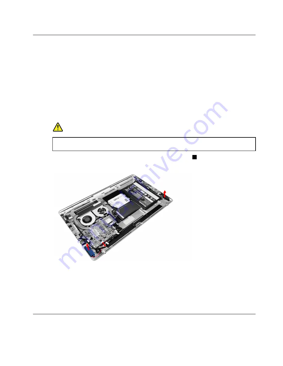
Step 6.

Disconnect the speaker cable from the connector on motherboard.

1

Step 7.

Lift up speaker system to remove it.

Step 8.

To install the new speaker system:

a.

Line up the new speaker system with the mounting holes on the rear cover, place the new
speaker system into position.

b.

Connect the new speaker cable to the connector on the motherboard.

c.

Reattach the battery to the rear cover.

Step 9.

Reattach the rear cover and secure it with the screw.

Replacing the power connector

Note:

Turn off the computer and wait 3 to 5 minutes to let it cool down before removing the rear cover.

Chapter 8

.

Replacing hardware

37

Содержание HORIZON 2s

Страница 1: ...Lenovo HORIZON 2s All In One PC Hardware Maintenance Manual Machine Types F0AT ...

Страница 2: ......

Страница 3: ...Lenovo HORIZON 2s All In One PC Hardware Maintenance Manual Machine Types F0AT ...

Страница 4: ...ght Lenovo 2014 2014 LIMITED AND RESTRICTED RIGHTS NOTICE If data or software are delivered pursuant a General Services Administration GSA contract use reproduction or disclosure is subject to restrictions set forth in Contract No GS 35F 05925 ...

Страница 5: ... FRU Index 19 Hard disk drive boot error 19 Power Supply Problems 19 POST error codes 20 Undetermined problems 20 Chapter 7 Locating connectors controls and components 21 Chapter 8 Replacing hardware 25 General information 25 Replacing the keyboard and mouse 26 Replacing the power adapter 26 Removing the rear cover 28 Replacing the battery 30 Replacing the hard disk drive 31 Replacing the Wi Fi ca...

Страница 6: ...iv Lenovo HORIZON 2s All In One PC Hardware Maintenance Manual ...

Страница 7: ...ION and DANGER sections in this manual before following any of the instructions Veuillez lire toutes les consignes de type DANGER et ATTENTION du présent document avant d exécuter les instructions Lesen Sie unbedingt alle Hinweise vom Typ ACHTUNG oder VORSICHT in dieser Dokumentation bevor Sie irgendwelche Vorgänge durchführen Leggere le istruzioni introdotte da ATTENZIONE e PERICOLO presenti nel ...

Страница 8: ...2 Lenovo HORIZON 2s All In One PC Hardware Maintenance Manual ...

Страница 9: ...rom areas that people may walk through to ensure no one trips over it Do not wear loose clothing that can be trapped in the moving parts of a machine Ensure that your sleeves are fastened or rolled up above your elbows If your hair is long tie or fasten it back Insert the ends of your necktie or scarf inside clothing or fasten it with a nonconductive clip approximately 8 centimeters 3 inches from ...

Страница 10: ... be a complete circuit to cause electrical shock By observing the above rule you may prevent a current from passing through your body When using a tester set the controls correctly and use the approved probe leads and accessories for that tester Stand on suitable rubber mats obtained locally if necessary to insulate you from grounds such as metal floor strips and machine frames Observe the special...

Страница 11: ...connect the power cord 3 Check the power cord for a A third wire ground connector in good condition Use a meter to measure third wire ground continuity for 0 1 ohm or less between the external ground pin and frame ground b The power cord should be the appropriate type as specified in the parts listings c Insulation must not be frayed or worn 4 Remove the cover 5 Check for any obvious alterations U...

Страница 12: ...l grounding of the computer is required for operator safety and correct system function Proper grounding of the electrical outlet can be verified by a certified electrician Safety notices The CAUTION and DANGER safety notices in this section are provided in the language of English DANGER Electrical current from power telephone and communication cables is hazardous To avoid a shock hazard Do not co...

Страница 13: ...row into or immerse in water Heat to more than 100 C 212 F Repair or disassemble Dispose of the battery as required by local ordinances or regulations CAUTION When laser products such as CD ROMs DVD ROM drives fiber optic devices or transmitters are installed note the following Do not remove the covers Removing the covers of the laser product could result in exposure to hazardous laser radiation T...

Страница 14: ...urn off the electrical current supplied to the device The device also might have more than one power cord To remove all electrical current from the device ensure that all power cords are disconnected from the power source 1 2 CAUTION Do not place any object weighing more than 82 kg 180 lbs on top of rack mounted devices 8 Lenovo HORIZON 2s All In One PC Hardware Maintenance Manual ...

Страница 15: ... for your computer This section lists the physical specifications for your computer Type Lenovo HORIZON 2s This section lists the physical specifications Environment Air temperature Operating 10 to 35 C Transit 20 to 55 C Humidity Operating 35 to 80 Transit 20 to 90 40 C Altitude 86KPa to 106KPa Electrical input Input voltage 90V 264V AC Input frequency 47Hz 63Hz Copyright Lenovo 2014 2014 9 ...

Страница 16: ...10 Lenovo HORIZON 2s All In One PC Hardware Maintenance Manual ...

Страница 17: ...dure to help determine the cause of the problem 1 Power off the computer and all external devices 2 Check all cables and power cords 3 Set all display controls to the middle position 4 Power on all external devices 5 Power on the computer Look for displayed error codes Look for readable instructions or a main menu on the display If you did not receive the correct response proceed to step 6 If you ...

Страница 18: ...12 Lenovo HORIZON 2s All In One PC Hardware Maintenance Manual ...

Страница 19: ...Starting the Setup Utility program You must use the keyboard when using the Lenovo BIOS Setup Utility menu The keys used to perform various tasks are displayed on the bottom of each screen Using passwords You can use the Lenovo BIOS Setup Utility program to set passwords to prevent unauthorized persons from gaining access to your computer and data See Starting the Setup Utility program The followi...

Страница 20: ...enovo BIOS Setup Utility program menu and select the Exit option 6 Select Save Changes and Exit from the menu To change an Administrator Password do the following 1 Start the Lenovo BIOS Setup Utility program see Starting the Lenovo BIOS Setup Utility program on page 13 2 From the Security menu select Set Administrator Password and press the Enter key 3 The password dialog box will be displayed Ty...

Страница 21: ...ayed Type the current password then press the Enter key 4 Type the new password then press the Enter key Retype the new password to confirm it If you typed the new password correctly the new password will be installed A Setup Notice will be displayed confirming that your changes have been saved 5 Return to the Lenovo BIOS Setup Utility program menu and select the Exit option 6 Select Save Changes ...

Страница 22: ...t Network Setup press the Enter key then select Onboard Ethernet Support or LAN Boot Agent 4 Select Disabled or Enabled and press the Enter key 5 Return to the Lenovo BIOS Setup Utility program menu and select the Exit option 6 Select Save Changes and Exit from the menu Notes a If you do not want to save the settings select Discard Changes and Exit from the menu Selecting a startup device If your ...

Страница 23: ...operating system before Windows 8 on your computer you must change the boot mode to Legacy support The legacy Windows operating system cannot be installed if you don t change the boot mode To change the booting mode do the following 1 Start the Lenovo BIOS Setup Utility program see Starting the Lenovo BIOS Setup Utility program on page 13 2 From the Lenovo BIOS Setup Utility program main menu sele...

Страница 24: ...18 Lenovo HORIZON 2s All In One PC Hardware Maintenance Manual ...

Страница 25: ...disk drive boot error A hard disk drive boot error can have the following causes Error FRU Action The startup drive is not included in the boot sequence configuration Check the configuration and ensure the startup drive is in the boot sequence No operating system is installed on the boot drive Install an operating system on the boot drive The boot sector on the startup drive is corrupted The drive...

Страница 26: ... and set the option to Enabled The BIOS then ignores the missing keyboard during POST Reboot and Select proper Boot device or Insert Boot Media in selected Boot device The BIOS was unable to find a suitable boot device Make sure the boot drive is properly connected to the computer Make sure you have bootable media in the boot device Undetermined problems 1 Power off the computer 2 Remove or discon...

Страница 27: ...he following illustration shows the location of controls and components on the front of the computer Attention Be careful not to block any air vents on the computer Blocked air vents can cause overheating 1 2 3 4 5 1 6 1 Built in microphone 4 Ambient light sensor 2 Camera LED indicator 5 Windows button 3 Built in camera 6 Near Field Communication NFC Copyright Lenovo 2014 2014 21 ...

Страница 28: ...omponents on the left and right side of the computer 1 3 4 5 6 8 7 2 1 Combo audio jack 5 Volume down up 2 USB 3 0 connectors 2 6 Battery status indicator 3 Power connector 7 Power button 4 Memory card reader 8 Power status indicator 22 Lenovo HORIZON 2s All In One PC Hardware Maintenance Manual ...

Страница 29: ...following illustration shows the location of connectors and components on the rear of the computer 1 2 1 1 3 1 Air vents 2 Computer stand 3 Charging connector Chapter 7 Locating connectors controls and components 23 ...

Страница 30: ...24 Lenovo HORIZON 2s All In One PC Hardware Maintenance Manual ...

Страница 31: ...the Safety and Warranty Guide go to the Support Web site at http support lenovo com Note Use only parts provided by Lenovo General information Pre disassembly instructions Before starting the disassembly procedure make sure that you do the following 1 Turn off the power to the system and all peripherals 2 Unplug all power and signal cables from the computer 3 Place the system on a flat stable surf...

Страница 32: ...Rear view for help with locating the various connectors Note Your keyboard will be connected to a USB connector on one side or at the rear of the computer Step 4 Disconnect the defective keyboard cable from the computer and connect the new keyboard cable to the same connector Note The mouse can be replaced using the same method Replacing the power adapter To replace the power adapter Step 1 Remove...

Страница 33: ...Step 3 Disconnect the failing power adapter from the computer Step 4 To install the new power adapter a Connect the new power adapter to the same connector Chapter 8 Replacing hardware 27 ...

Страница 34: ...memory cards from the drives shut down the operating system and turn off the computer and all attached devices Step 2 Unplug all power cords from electrical outlets Step 3 Disconnect all cables attached to the computer This includes power cords input output I O cables and any other cables that are connected to the computer Refer to Left and right view and Rear view for help with locating the vario...

Страница 35: ...sk 2 Step 7 Put the head of crowbar or boot disk into the slot in between the panel and the rear cover as shown The panel and rear cover are pinned together work around the edge to release the panel from the rear cover 1 then prise the rear cover away from the panel 2 Chapter 8 Replacing hardware 29 ...

Страница 36: ...f the computer and wait 3 to 5 minutes to let it cool down before removing the base cover To replace the battery Step 1 Remove any media disks CDs DVDs or memory cards from the drives shut down the operating system and turn off the computer and all attached devices Step 2 Unplug all power cords from electrical outlets Step 3 Disconnect all cables attached to the computer This includes power cords ...

Страница 37: ...g the rear cover To replace the hard disk drive Step 1 Remove any media disks CDs DVDs or memory cards from the drives shut down the operating system and turn off the computer and all attached devices Step 2 Unplug all power cords from electrical outlets Step 3 Disconnect all cables attached to the computer This includes power cords input output I O cables and any other cables that are connected t...

Страница 38: ...onnector on the hard disk drive Step 10 To install the new hard disk drive a Connect the power and data cable to the connector on the new hard disk drive b Attach the new hard disk drive to the bracket and secure them with the four screws c Place the new hard disk drive assembly into the hard disk drive bay d Secure the assembly to the rear cover with the four screws e Reconnect the battery cable ...

Страница 39: ... Step 5 Disconnect the battery power cable from the connector on the motherboard DANGER Disconnect the battery power cable from the connector on the motherboard before proceeding replacing any parts to avoid electric shock Step 6 Remove the screw that secures the Wi Fi card to the motherboard Step 7 Disconnect the antenna and data cables from the Wi Fi card Step 8 Pull the Wi Fi card upward to rem...

Страница 40: ...replacing any parts to avoid electric shock Step 6 Remove the sealing tape as shown 1 Step 7 Remove the five screws that secure the heat sink module to the motherboard Step 8 Lift up the heat sink to remove it Attention Place the heat sink upside down on a flat surface to prevent thermal grease contaminating other components Step 9 To install the new heat sink a Use an alcohol pad to wipe the ther...

Страница 41: ...he rear cover Step 5 Disconnect the battery power cable from the connector on the motherboard DANGER Disconnect the battery power cable from the connector on the motherboard before proceeding replacing any parts to avoid electric shock Step 6 Disconnect the power cable from the connector on the motherboard 1 Step 7 Remove the three screws that secure the system fans to the rear cover Step 8 Lift u...

Страница 42: ...the rear cover Step 5 Disconnect the battery power cable from the connector on the motherboard DANGER Disconnect the battery power cable from the connector on the motherboard before proceeding replacing any parts to avoid electric shock Step 6 Disconnect the data cable from the I O board 1 Step 7 Remove the two screws that secure the I O board to the rear cover Step 8 Slide the I O board and then ...

Страница 43: ...over Refer to Removing the rear cover Step 5 Remove the battery Refer to Replacing the battery DANGER Disconnect the battery power cable from the connector on the motherboard before proceeding replacing any parts to avoid electric shock Step 6 Disconnect the speaker cable from the connector on motherboard 1 Step 7 Lift up speaker system to remove it Step 8 To install the new speaker system a Line ...

Страница 44: ...onnector on the motherboard before proceeding replacing any parts to avoid electric shock Step 6 Disconnect the data cable from the connector on the motherboard 1 Step 7 Remove the screw that secures the connector to the rear cover Step 8 Lift up the power connector to remove it Step 9 To install the new power connector a Connect the data cable to the connector on the motherboard b Line up the pow...

Страница 45: ...sconnect the data cable from the connector on the motherboard 1 Step 7 Lift up the dongle connector to remove it Step 8 To install the new dongle connector a Connect the data cable to the connector on the motherboard b Line up the dongle connector with the mounting bay on the rear cover then place the dongle connector into position and secure the dongle connector to the rear cover with the double ...

Страница 46: ...g board cable to the connector on the motherboard b Line up the power docking board with the mounting holes on the rear cover then place the power docking board into position and secure it with the screws c Reconnect the battery cable to the connector on the motherboard Step 10 Reattach the rear cover and secure it with the screw Replacing the button board Note Turn off the computer and wait 3 to ...

Страница 47: ...board c Reconnect the battery cable to the connector on the motherboard Step 10 Reattach the rear cover and secure it with the screw Replacing the motherboard Note Turn off the computer and wait 3 to 5 minutes to let it cool down before removing the rear cover To replace the motherboard Step 1 Remove any media disks CDs DVDs or memory cards from the drives shut down the operating system and turn o...

Страница 48: ... with the mounting holes on the rear cover and secure the new motherboard with the five screws b Attach the heat sink Wi Fi card and system fan to the new motherboard c Connect all the cables to the new motherboard DANGER Connect the battery cable to the connector on the motherboard lastly to avoid electric shock Step 12 Reattach the rear cover and secure it with the screw Replacing the camera Not...

Страница 49: ...he computer and wait 3 to 5 minutes to let it cool down before removing the rear cover To replace the LED panel module Step 1 Remove any media disks CDs DVDs or memory cards from the drives shut down the operating system and turn off the computer and all attached devices Step 2 Unplug all power cords from electrical outlets Step 3 Disconnect all cables attached to the computer This includes power ...

Страница 50: ...onnect the LVDS cable to the connector and touch control board b Reattach the camera to the front bezel c Connect the LVDS cable to the connectors on the LED panel d Connect the cable to the connectors on the transform board e Attach the camera to the new LED panel module Step 11 Reattach the rear cover and secure it with the screw 44 Lenovo HORIZON 2s All In One PC Hardware Maintenance Manual ...

Страница 51: ...B 5B20G05110 W8P M i7 4510U 8G MB 5B20G05107 NOK M i5 4210U 8G MB 5B20G00905 W8S M i5 4210U 8G MB 5B20G00895 W8P M i5 4210U 8G MB 5B20G00894 NOK M i5 4210U 4G MB 5B20G00899 W8S M i5 4210U 4G MB 5B20G00898 W8P M i5 4210U 4G MB 5B20G00897 NOK M i3 4030U 4G MB 5B20G00902 W8S M i3 4030U 4G MB 5B20G00903 W8P M i3 4030U 4G MB 5B20G00904 NOK M i3 4010U 4G MB 5B20G00896 W8S M i3 4010U 4G MB 5B20G00900 W8P...

Страница 52: ... 5C10F66829 Beta II windows key cable 5C10F66830 Beta II WD HDD cable 5C10F66819 Beta II Seagate HDD cable 5C10F66820 Beta II Seagate HDD cable 5C10F66820 N Power DELTA ADP 90XD BC 90W common adapter 36200415 Liteon PA 1900 72IA 90w common adapter 36200416 1 Battery sanyo MSI Beta II 19 5 battery 31507327 simplo MSI Beta II 19 5 battery 31507328 N Wifi Liteon HFA345 QCA9965 1x1ac BT4 0 M 2 Combo 2...

Страница 53: ...61 RU 2 4G KB improved8 25216256 Liteon SK 8861 GB 2 4G KB improved8 25216257 Liteon SK 8861 Nordic 2 4G KB improved8 25216258 Liteon SK 8861 LA 2 4G KB improved8 25216259 Liteon SK 8861 SA 2 4G KB improved8 25216261 Liteon SK 8861 DE 2 4G KB improved8 25216262 Liteon SK 8861 TR 2 4G KB improved8 25216263 Liteon SK 8861 ES 2 4G KB improved8 25216264 Liteon SK 8861 IT 2 4G KB improved8 25216265 Lit...

Страница 54: ...ongwell B LAck single head 1 0M India Power Cord 31035395 Luxshare 1 0M C5 India Power Cord 31503353 Longwell B LAck single head 1 0M Italy C5 Power Cord 31039104 Volex 1 0M C5 Italy Power Cord 31049504 Luxshare 1 0M C5 Italy Power Cord 31503359 Longwell B LAck single head 1 0M Brazil Power Cord 31035828 Volex 1 0M C5 Brazil Power Cord 31049505 Luxshare 1 0M C5 Brazil Power Cord 31503357 Longwell ...

Страница 55: ...ord 31049499 Longwell B LAck single head 1 0M Korea C5 Power Cord 31039106 Volex 1 0M C5 Korea Power Cord 31049498 Luxshare 1 0M C5 Korea Power Cord 31503358 Longwell B LAck single head 1 0M SA C5 Power Cord 31039105 Volex 1 0M C5 South Africa Power Cord 31049501 Luxshare 1 0M C5 South Africa Power Cord 31503355 Chapter 9 FRU lists 49 ...

Страница 56: ...50 Lenovo HORIZON 2s All In One PC Hardware Maintenance Manual ...

Страница 57: ... is allowed to control the power management features of the computer and the settings for Advanced Power Management APM BIOS mode is ignored Not all operating systems support ACPI BIOS mode Automatic Power On features The Automatic Power On features within the Power Management menu allow you to enable and disable features that turn on the computer automatically Wake Up on Alarm You can specify a d...

Отзывы: