Flex System X6 Compute Node (7903)
21
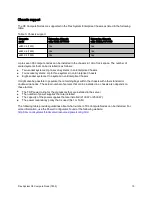
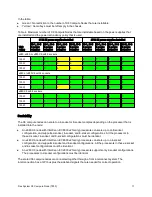
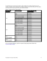
A compatible switch or pass-through module must be installed in the corresponding I/O bays in the
chassis, as indicated in the following table. Installing two switches means that all the ports of the adapter
are enabled, which improves performance and network availability.
Table 11. Adapter to I/O bay correspondence
I/O adapter slot
in the server
Port on the adapter
Corresponding I/O module
bay in the chassis
Port 1
Module bay 1
Port 2
Module bay 2
Port 3 (for 4 & 8-port cards)
Module bay 1
Port 4 (for 4 & 8-port cards)
Module bay 2
Port 5 (for 8-port cards)
Module bay 1
Port 6 (for 8-port cards)
Module bay 2
Port 7 (for 8-port cards)
Module bay 1
Slot 1
Port 8 (for 8-port cards)
Module bay 2
Port 1
Module bay 3
Port 2
Module bay 4
Port 3 (for 4 & 8-port cards)
Module bay 3
Port 4 (for 4 & 8-port cards)
Module bay 4
Port 5 (for 8-port cards)
Module bay 3
Port 6 (for 8-port cards)
Module bay 4
Port 7 (for 8-port cards)
Module bay 3
Slot 2
Port 8 (for 8-port cards)
Module bay 4
Port 1
Module bay 1
Slot 3
(Dual-ASIC adapters
are not supported.)
Port 2
Module bay 2
Port 1
Module bay 3
Slot 4
(Dual-ASIC adapters
are not supported.)
Port 2
Module bay 4
For a list of supported switches, see the Flex System Interoperability Guide, available from:
http://lenovopress.com/fsig

