

This section shows how the Cisco Catalyst Switch Module 3012 can be used in configurations.
Basic two-port configuration
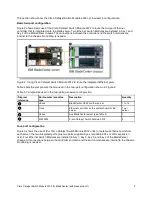
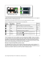
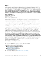
Figure 2 shows basic use of the Cisco Catalyst Switch Module 3012 to route the two-port Ethernet
controller that is integrated onto the blade server. Two Ethernet Switch Modules are installed in bay 1 and
bay 2 of the BladeCenter chassis. The connections between the controller and the switch modules are
internal to the chassis. No cabling is needed.
Figure 2. Using Cisco Catalyst Switch Module 3012 to route the integrated Ethernet ports
Table 4 lists the components that are used in the two-port configuration shown in Figure 2.
Table 4. Components used in the two-ports-per-server configuration
Diagram
reference
Part number / machine
type
Description
Quantity
Varies
BladeCenter HS22 or other server
1 to 14
None
Ethernet controller on the system board of the
server
1 per
server
Varies
Any BladeCenter server (see Table 2)
1
43W4395
Cisco Catalyst Switch Module 3012
2
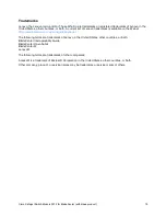
Four-port configuration
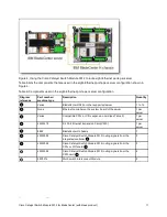
Figure 3 shows the use of four Cisco Catalyst Switch Module 3012 units to route four Ethernet ports from
each server: the two integrated ports plus two ports supplied by a compatible CFFv or CIOv expansion
card. Four Ethernet Switch Modules are installed in bay 1, bay 2, bay 3, and bay 4 of the BladeCenter
chassis. All connections between the controller and card and the switch modules are internal to the chassis.
No cabling is needed.
Cisco Catalyst Switch Module 3012 for BladeCenter (withdrawn product)
9


