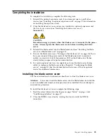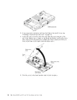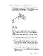
background image

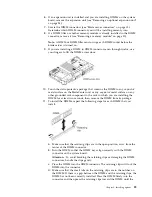
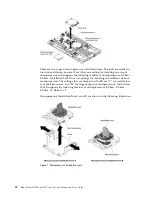
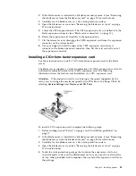
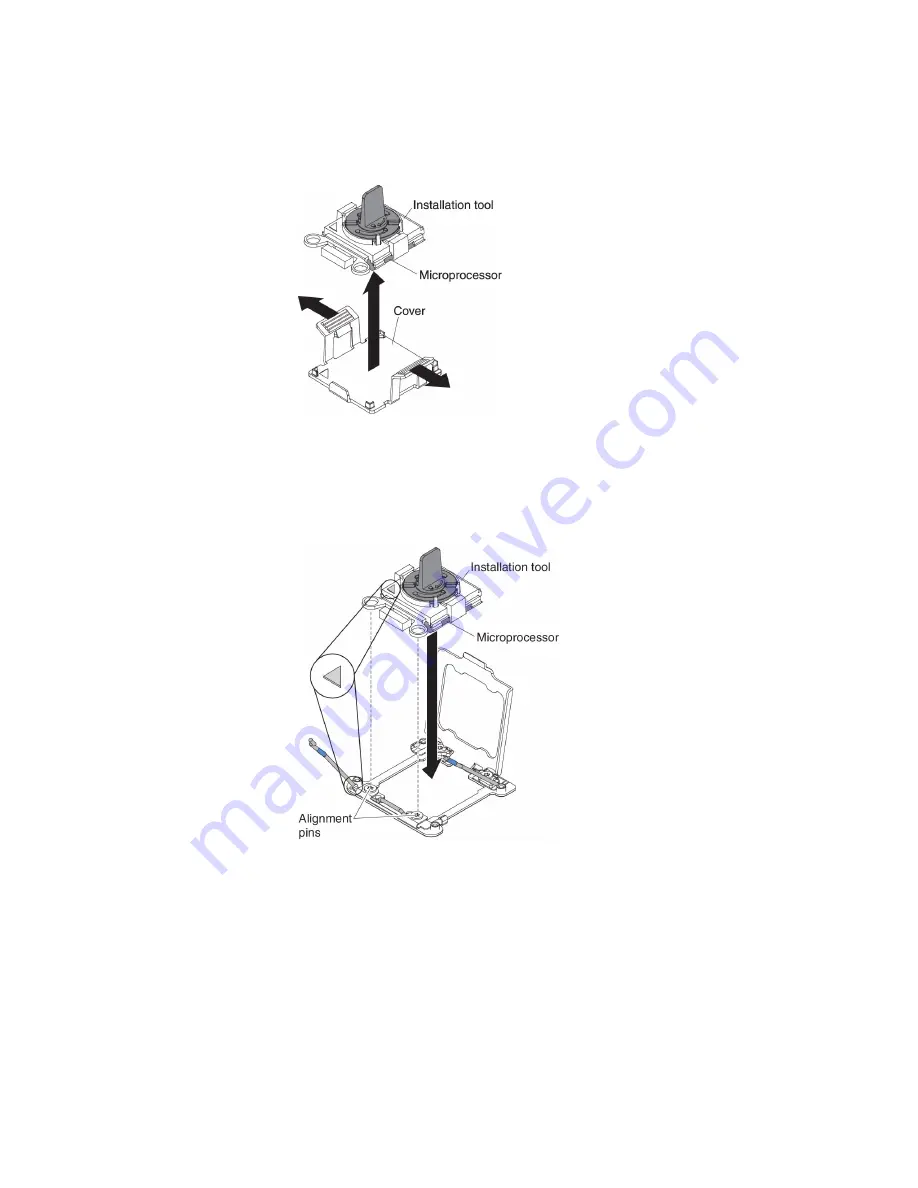
surface on any other grounded rack component; then, carefully remove the
microprocessor and the installation tool from the package.

c.

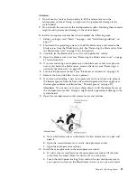
Release the sides of the cover and remove the cover from the installation
tool. The microprocessor is preinstalled on the installation tool.

Note:

Do not touch the microprocessor contacts. Contaminants on the

microprocessor contacts, such as oil from your skin, can cause connection
failures between the contacts and the socket.

d.

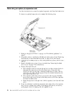
Align the installation tool with the microprocessor socket. The installation
tool rests flush on the socket only if properly aligned.

e.

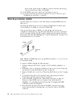
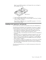
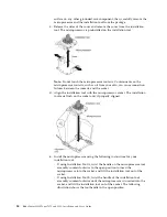
Install the microprocessor using the following instructions for your
installation tool.

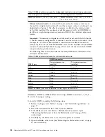
v

If using Installation Tool A, twist the handle on the microprocessor tool
assembly counterclockwise to the open position to insert the
microprocessor into the socket, and lift the installation tool out of the
socket.

v

If using Installation Tool B, twist the handle of the installation tool
assembly counterclockwise until the microprocessor is inserted into the
socket, and lift the installation tool out of the socket. The following
illustration shows the tool handle in the open position.

34

BladeCenter HS23 Types 7875 and 1929: Installation and User's Guide

Содержание BladeCenter HS23

Страница 1: ...Lenovo BladeCenter HS23 Types 7875 and 1929 Installation and User s Guide Machine Type Types 7875 and 1929 ...

Страница 2: ...y Information and the Environmental Notices and User Guide documents on the IBM Documentation CD The most recent version of this document is available at http www ibm com supportportal Fourth Edition December 2013 Copyright IBM Corporation 2013 US Government Users Restricted Rights Use duplication or disclosure restricted by GSA ADP Schedule Contract with IBM Corp ...

Страница 3: ...alling the blade server in a BladeCenter unit 47 Updating the blade server configuration 49 Input output connectors and devices 49 Chapter 4 Configuring the blade server 51 Using the Setup utility 52 Setup utility menu 52 Using passwords 56 Using the ServerGuide Setup and Installation CD 56 ServerGuide features 57 Setup and configuration overview 57 Typical operating system installation 58 Install...

Страница 4: ... statement 82 Germany Class A statement 83 Japan VCCI Class A statement 84 Japan Electronics and Information Technology Industries Association JEITA statement 84 Korea Communications Commission KCC statement 84 Russia Electromagnetic Interference EMI Class A statement 85 People s Republic of China Class A electronic emission statement 85 Taiwan Class A compliance statement 85 Index 87 iv BladeCent...

Страница 5: ...odukt Lees voordat u dit product installeert eerst de veiligheidsvoorschriften Ennen kuin asennat tämän tuotteen lue turvaohjeet kohdasta Safety Information Avant d installer ce produit lisez les consignes de sécurité Vor der Installation dieses Produkts die Sicherheitshinweise lesen Prima di installare questo prodotto leggere le Informazioni sulla Sicurezza Copyright IBM Corp 2013 v ...

Страница 6: ...roduktet Antes de instalar este produto leia as Informações sobre Segurança Antes de instalar este producto lea la información de seguridad Läs säkerhetsinformationen innan du installerar den här produkten vi BladeCenter HS23 Types 7875 and 1929 Installation and User s Guide ...

Страница 7: ...l the device Statement 1 DANGER Electrical current from power telephone and communication cables is hazardous To avoid a shock hazard v Do not connect or disconnect any cables or perform installation maintenance or reconfiguration of this product during an electrical storm v Connect all power cords to a properly wired and grounded electrical outlet v Connect to properly wired outlets any equipment...

Страница 8: ...turer The battery contains lithium and can explode if not properly used handled or disposed of Do not v Throw or immerse into water v Heat to more than 100 C 212 F v Repair or disassemble Dispose of the battery as required by local ordinances or regulations Statement 3 CAUTION When laser products such as CD ROMs DVD drives fiber optic devices or transmitters are installed note the following v Do n...

Страница 9: ...t 4 CAUTION Use safe practices when lifting 18 kg 39 7 lb 32 kg 70 5 lb 55 kg 121 2 lb Statement 8 CAUTION Never remove the cover on a power supply or any part that has the following label attached Hazardous voltage current and energy levels are present inside any component that has this label attached There are no serviceable parts inside these components If you suspect a problem with one of thes...

Страница 10: ...uit protection requirements Refer to the information that is provided with your device for electrical specifications Statement 21 CAUTION Hazardous energy is present when the blade is connected to the power source Always replace the blade cover before installing the blade Statement 32 CAUTION To avoid personal injury before lifting the unit remove all the blades power supplies and removable module...

Страница 11: ...rrent from the device ensure that all power cords are disconnected from the power source Rack Safety Information Statement 2 DANGER v Always lower the leveling pads on the rack cabinet v Always install stabilizer brackets on the rack cabinet v Always install servers and optional devices starting from the bottom of the rack cabinet v Always install the heaviest devices in the bottom of the rack cab...

Страница 12: ...xii BladeCenter HS23 Types 7875 and 1929 Installation and User s Guide ...

Страница 13: ...vice drivers and install the operating system To download the latest device drivers go to http www ibm com supportportal The blade server comes with a limited warranty For information about the terms of the warranty and getting service and assistance see the Warranty Information document for your blade server You can obtain up to date information about the blade server at http www ibm com systems ...

Страница 14: ...abel on the blade server itself or in any way block the ventilation holes on the blade server A set of blank labels for your blade server comes with the BladeCenter unit When you install the blade server in the BladeCenter unit write identifying information on a label and place the label on the BladeCenter unit bezel See the documentation for your BladeCenter unit for recommended label placement 2...

Страница 15: ...all non device specific events and recommended actions sorted by event ID Device specific event information is in the documentation for the device v Advanced Management Module Command Line Interface Reference Guide This document explains how to use the advanced management module command line interface CLI to directly access the BladeCenter management functions The command line interface also provi...

Страница 16: ...f The Documentation Browser automatically detects the regional settings in use in your system and displays the documents in the language for that region if available If a document is not available in the language for that region the English language version is displayed Use one of the following procedures to start the Documentation Browser v If Autostart is enabled insert the CD into the CD drive ...

Страница 17: ...The caution and danger statements in this document are also in the multilingual Safety Information document which is on the IBM Documentation CD Each statement is numbered for reference to the corresponding statement in the Safety Information document The following notices and statements are used in this document v Note These notices provide important tips guidance or advice v Important These noti...

Страница 18: ... advanced system management are provided by the BladeCenter unit 2 The operating system in the blade server must provide USB support for the blade server to recognize and use USB media drives and devices The BladeCenter unit uses USB for internal communications with these devices The following table is a summary of the features and specifications of the blade server 6 BladeCenter HS23 Types 7875 a...

Страница 19: ...0 ft Blade server on 10 C to 32 C 50 F to 89 6 F Altitude 914 4 m to 2133 6 m 3000 ft to 7000 ft Blade server off 10 C to 43 C 50 F to 109 4 F Altitude 914 4 m to 2133 6 m 3000 ft to 7000 ft Blade server shipping 40 C to 60 C 40 F to 140 F v Humidity Blade server on 8 to 80 Blade server off 8 to 80 Blade server storage 5 to 80 Blade server shipment 5 to 100 v E5 2697 V2 and E5 2690 V2 will reach t...

Страница 20: ...es programs to help you set up the blade server and install a Windows operating system The ServerGuide program detects installed optional hardware devices and provides the correct configuration programs and device drivers For more information about the ServerGuide Setup and Installation CD see Using the ServerGuide Setup and Installation CD on page 56 v Microprocessor technology The blade server s...

Страница 21: ...ent by using the Advanced Management Module For more information about configuring and using power throttling see the Advanced Management Module documentation or http www ibm com supportportal Reliability availability and serviceability features Reliability availability and serviceability features help to ensure the integrity of the data that is stored in the blade server the availability of the b...

Страница 22: ...ent diagnostics v Service processor that communicates with the Advanced Management Module to enable remote blade server management v System error logging v Vital product data VPD on memory v Wake on LAN capability v Wake on PCI PME capability v Wake on USB 2 0 capability Major components of the blade server Use this information to locate the major components on the blade server The following illus...

Страница 23: ... installed If the LED continues to flash rapidly the blade server might not have power permissions assigned to it through the Advanced Management Module AMM the BladeCenter unit does not have enough power to turn on the blade server or the service processor IMM2 on the blade server is not communicating with the AMM v Flashing slowly The blade server has power supplied and is ready to be turned on ...

Страница 24: ...button Press this button to associate the shared BladeCenter unit keyboard port video port and mouse port with the blade server The LED on this button flashes while the request is being processed and then is lit when the ownership of the keyboard video and mouse has been transferred to the blade server It can take approximately 20 seconds to switch the keyboard video and mouse control to the blade...

Страница 25: ...response when you press the media tray select button you can use the Advanced Management Module Web interface to determine whether local control has been disabled on the blade server Note The operating system in the blade server must provide USB support for the blade server to recognize and use the removable media drives The following illustration identifies the information LEDs on the SAS hot swa...

Страница 26: ...feature has not been disabled through the management module the Wake on LAN feature can turn on the blade server Turning off the blade server Use this information to turn off the blade server When you turn off the blade server it is still connected to power through the BladeCenter unit The blade server can respond to requests from the service processor such as a remote request to turn on the blade...

Страница 27: ... blade server system board components and connectors for optional devices The following illustration shows the system board components including connectors for user installable optional devices in the blade server Chapter 2 Power controls and indicators 15 ...

Страница 28: ...16 BladeCenter HS23 Types 7875 and 1929 Installation and User s Guide ...

Страница 29: ...working Place removed covers and other parts in a safe place v Back up all important data before you make changes to disk drives v Before you remove a blade server from the BladeCenter unit you must shut down the operating system and turn off the blade server You do not have to shut down the BladeCenter unit itself v Blue on a component indicates touch points where you can grip the component to re...

Страница 30: ...ges until you are ready to install them To reduce the possibility of damage from electrostatic discharge observe the following precautions v When you work on a BladeCenter unit that has an electrostatic discharge ESD connector use a wrist strap especially when you handle modules optional devices or blade servers To work correctly the wrist strap must have a good contact at both ends touching your ...

Страница 31: ...ewly installed devices 4 Save the DSA log as a file and send it to IBM For information about transferring data and logs see http publib boulder ibm com infocenter toolsctr v1r0 index jsp topic dsa dsa_main html 5 To ship the server repackage it in the original undamaged packing material and observe IBM procedures for shipping Support information for IBM Business Partners is available at http www i...

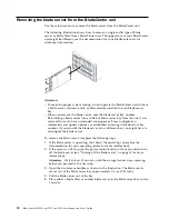
Страница 32: ... update options are established according to blade server bay number if you reinstall the blade server into a different bay you might have to reconfigure the blade server To remove the blade server complete the following steps 1 If the blade server is operating shut down the operating system see the documentation for your operating system for more information 2 If the server is still on press the ...

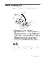
Страница 33: ...e blade server from the BladeCenter unit on page 20 for instructions 3 Carefully lay the blade server on a flat static protective surface with the cover side up 4 Press the blade server cover release on each side of the blade server or expansion unit and lift the cover open as shown in the illustration 5 Lay the cover flat or lift it from the blade server and store for future use Statement 21 CAUT...

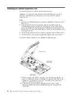
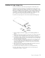
Страница 34: ...ladeCenter unit to power the blade bays in which you install the blade server and expansion units 3 The following illustration shows an optional expansion unit in a blade server 4 The illustrations in this document might differ slightly from your hardware To install an optional expansion unit complete the following steps 1 Before you begin read Safety on page v and Installation guidelines on page ...

Страница 35: ...o that the slots at the rear slide down onto the cover pins at the rear of the blade server then pivot the expansion unit down onto the blade server 8 If the expansion unit has an extraction device such as a thumbscrew or a lever use it to fully engage the expansion unit on the blade server otherwise press the expansion unit firmly into the closed position until it clicks into place To install an ...

Страница 36: ...e expansion unit has an extraction device use the extraction device to disengage the expansion unit from the blade server These extraction devices can be of several types including thumbscrews or levers See the instructions provided with the expansion unit for detailed instructions for removing the expansion unit b If the expansion unit does not have an extraction device press the blade server cov...

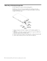
Страница 37: ...tify the storage bay storage bay 0 or storage bay 1 in which the hot swap storage drive will be installed see Blade server connectors on page 15 3 If a storage bay filler is installed remove it from the blade server by pulling the release lever and sliding the filler away from the blade server see Removing a hot swap storage drive on page 26 4 Touch the static protective package that contains the ...

Страница 38: ...ete the following steps 1 Before you begin read Safety on page v and Installation guidelines on page 17 2 If possible save the data on your drive especially if it is part of a RAID array before you remove it from the blade server 3 Press the release latch orange on the storage drive to release the drive handle 4 Pull the release handle to remove the drive from the storage bay 26 BladeCenter HS23 T...

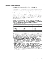
Страница 39: ...el 0 7 and 8 15 and 16 Channel 1 1 and 2 13 and 14 Channel 2 3 and 4 9 and 10 Channel 3 5 and 6 11 and 12 Depending on the memory mode that is set in the Setup utility the blade server can support a minimum of 4 GB and a maximum of 128 GB of system memory on the system board in a blade server with one microprocessor If two microprocessors are installed the blade server can support a minimum of 8 G...

Страница 40: ...hich DIMM connectors belong to the channel The following table shows the order that memory DIMMs are installed to use a mirrored channel mode Table 4 DIMM population sequence for mirrored channel mode DIMM pair DIMM connectors One microprocessor installed Two microprocessors installed First 1 and 7 1 and 7 Second 3 and 5 14 and 16 Third 2 and 8 3 and 5 Fourth 4 and 6 9 and 11 Fifth None 2 and 8 Si...

Страница 41: ...ed metal surface on any other grounded rack component in the rack in which you are installing the DIMM for at least two seconds then remove the DIMM from its package 11 To install the DIMMs repeat the following steps for each DIMM that you install a Make sure that the retaining clips are in the open position away from the center of the DIMM connector b Turn the DIMM so that the DIMM keys align cor...

Страница 42: ... more information to save changes Note DIMMs or DIMM fillers must occupy DIMM connectors 1 2 13 14 15 and 16 for proper cooling To remove a DIMM complete the following steps 1 Before you begin read Safety on page v and Installation guidelines on page 17 2 If the blade server is installed in a BladeCenter unit remove it see Removing the blade server from the BladeCenter unit on page 20 3 Remove the...

Страница 43: ...rocessor and heat sink If the blade server has only one microprocessor it must be installed in microprocessor socket 1 v If you are installing a second microprocessor make sure that the microprocessors are identical v Before you install a new microprocessor download and install the most current level of UEFI code see Updating firmware and device drivers on page 60 v When you install a second micro...

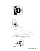
Страница 44: ... for installing two different sizes of microprocessors The settings that are marked on Tool B are L for smaller low core microprocessors and H for larger high core microprocessors Installation Tool B supports the following families of microprocessors E5 26xx E5 46xx E5 26xx v2 E5 46xx v2 Microprocessor Installation Tools A and B are shown in the following illustration Figure 1 Microprocessor insta...

Страница 45: ...ving an optional expansion unit on page 24 6 Locate microprocessor socket 2 see Blade server connectors on page 15 7 Remove the heat sink filler if one is present 8 If you are not installing a new microprocessor and a new heat sink remove the thermal grease from the heat sink and microprocessor then apply new thermal grease before installation see Thermal grease on page 37 Attention Do not use any...

Страница 46: ...he installation tool rests flush on the socket only if properly aligned e Install the microprocessor using the following instructions for your installation tool v If using Installation Tool A twist the handle on the microprocessor tool assembly counterclockwise to the open position to insert the microprocessor into the socket and lift the installation tool out of the socket v If using Installation...

Страница 47: ...ly in the socket before you try to close the microprocessor retainer v Do not touch the thermal material on the bottom of the heat sink or on top of the microprocessor Touching the thermal material will contaminate it 11 Close the microprocessor socket release levers and retainer Figure 2 Installation Tool B Figure 3 Installation tool handle adjustment Chapter 3 Installing options 35 ...

Страница 48: ...r alternating among the screws until they are tight If possible each screw should be rotated two full rotations at a time Repeat until the screws are tight Do not overtighten the screws by using excessive force If you are using a torque wrench tighten the screws to 8 5 Newton meters Nm to 13 Nm 6 3 foot pounds to 9 6 foot pounds 13 If you are installing a new heat sink complete the following steps...

Страница 49: ...owing steps 1 Place the heat sink assembly on a clean work surface 2 Remove the cleaning pad from its package and unfold it completely 3 Use the cleaning pad to wipe the thermal grease from the bottom of the heat sink Note Make sure that all of the thermal grease is removed 4 Use a clean area of the cleaning pad to wipe the thermal grease from the microprocessor then dispose of the cleaning pad af...

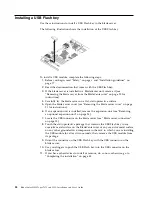
Страница 50: ...6 If an expansion unit is installed remove the expansion unit see Removing an optional expansion unit on page 24 7 Locate the USB connector on the blade server see Blade server connectors on page 15 8 Touch the static protective package that contains the USB Flash key to any unpainted metal surface on the BladeCenter unit or any unpainted metal surface on any other grounded rack component in the r...

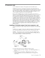
Страница 51: ...rnet switch modules two pass thru modules or one Ethernet switch module and one pass thru module in the BladeCenter unit Because pass thru modules are compatible with a variety of I O expansion cards installing two pass thru modules enables the use of several types of compatible I O expansion cards in blade servers within the same BladeCenter unit Installing a horizontal compact form factor expans...

Страница 52: ... on the expansion card and expansion connector on the system board then press the expansion card into the expansion connector 11 Firmly press on the indicated locations to seat the expansion card Note For device driver and configuration information to complete the installation of the expansion card see the documentation that comes with the expansion card 12 Rotate the expansion card standoffs to t...

Страница 53: ...server supports a vertical combination I O CIOv expansion card and a horizontal combination form factor CFFh expansion card The following illustration shows the location and installation of a CIOv expansion card Attention If the expansion card is not running at the speed supported by the card you can change the maximum speed of the PCIe bus in the Setup Utility by selecting System Settings and Dev...

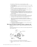
Страница 54: ...lustration shows how to remove a vertical combination I O CIOv expansion card To remove a CIOv expansion card complete the following steps 1 Before you begin read Safety on page v and Installation guidelines on page 17 2 If the blade server is installed in a BladeCenter unit remove it see Removing the blade server from the BladeCenter unit on page 20 for instructions 3 Carefully lay the blade serv...

Страница 55: ...ver cover on page 21 for instructions 5 Locate the blade server interposer card connector see Blade server connectors on page 15 6 If a horizontal combination form factor CFFh expansion card is installed on the expansion connector remove it see Removing a horizontal compact form factor expansion card on page 40 7 Touch the static protective package that contains the interposer card to any unpainte...

Страница 56: ... guidelines on page 17 2 If the blade server is installed in a BladeCenter unit remove it see Removing the blade server from the BladeCenter unit on page 20 for instructions 3 Carefully lay the blade server on a flat static protective surface 4 Open the blade server cover see Removing the blade server cover on page 21 for instructions 5 Locate the 10Gb interposer card 6 Rotate the expansion card s...

Страница 57: ...e power cords of the BladeCenter unit to electrical outlets you must wait until the power on LED on the blade server flashes slowly before you press the power control button 5 For certain optional devices you might have to run the blade server Setup utility to configure the blade server see Chapter 4 Configuring the blade server on page 51 See the documentation that comes with your optional device...

Страница 58: ...down onto the pins at the rear of the blade server as shown in the illustration Before you close the cover make sure that all components are installed and seated correctly and that you have not left loose tools or parts inside the blade server 5 Pivot the cover to the closed position until it clicks into place 46 BladeCenter HS23 Types 7875 and 1929 Installation and User s Guide ...

Страница 59: ...or device is in blade bay 7 through 14 power modules must be installed in all four power module bays For additional information see the Installation and User s Guide that comes with the BladeCenter unit b If you are reinstalling a blade server that you removed you must install it in the same blade bay from which you removed it Some blade server configuration information and update options are esta...

Страница 60: ... so now 9 Optional Write identifying information on one of the labels that come with the blade servers and place the label on the BladeCenter unit bezel See the documentation for your BladeCenter unit for information about the label placement Important Do not place the label on the blade server or in any way block the ventilation holes on the blade server If this is the initial installation of the...

Страница 61: ...g the operating system on page 67 and your operating system documentation for additional information Input output connectors and devices Use this information to locate the input output connectors and devices The input output connectors that are available to the blade server are supplied by the BladeCenter unit See the documentation that comes with the BladeCenter unit for information about the inp...

Страница 62: ...50 BladeCenter HS23 Types 7875 and 1929 Installation and User s Guide ...

Страница 63: ...e and walk away feature reduces the hands on server setup time from days to minutes particularly for larger deployments For information about this tool see http www ibm com support entry portal docdisplay lndocid TOOL FASTSET v IBM ServerGuide Setup and Installation CD The ServerGuide program provides software setup tools and installation tools that are designed for the blade server Use this CD du...

Страница 64: ...e following menu items are on the Setup utility main menu Depending on the version of the Unified Extensible Firmware Interface UEFI some menu items might differ slightly from these descriptions v System Information Select this choice to view information about the server When you make changes through other choices in the Setup utility some of those changes are reflected in the system information y...

Страница 65: ...annot detect it disabling a device is equivalent to disconnecting the device You can also choose to enable or disable adapter option ROM support Disabling support can potentially improve the time it takes the blade server to start Power Select this choice to view or change Active Energy Manager AEM power capping to control power consumption and processor performance states Operating Modes Select t...

Страница 66: ...the static IP address or have DHCP assign the IMM2 IP address save the network changes Restore IMM to Defaults Select this choice to restore the IMM2 to the default settings The IMM2 controller restarts after you restore the settings Reset IMM Select this choice to restart the IMM2 controller Recovery Select this choice to view or change recovery settings Storage Select this choice to view or chan...

Страница 67: ... error LED on the front of the blade server is lit but there are no other error indications clear the system event log Also after you complete a repair or correct an error clear the system event log to turn off the system error LED on the front of the blade server POST Event Viewer Select this choice to enter the POST event viewer to view the UEFI diagnostic codes System Event Log Select this choi...

Страница 68: ...Installation CD Use this information as an overview for using the ServerGuide Setup and Installation CD The ServerGuide Setup and Installation CD contains a setup and installation program that is designed for your blade server The ServerGuide program detects the blade server model and optional hardware devices that are installed and uses that information during setup to configure the hardware The ...

Страница 69: ...ation for supported Windows operating systems v Includes an online readme file with links to tips for the hardware and operating system installation Setup and configuration overview Use this information to setup and configure the blade server When you use the ServerGuide Setup and Installation CD you do not need setup diskettes You can use the CD to configure any supported IBM blade server model T...

Страница 70: ...ce drivers This information is stored and then passed to the operating system installation program 3 The ServerGuide program presents operating system partition options that are based on your operating system selection and the installed hard disk drives 4 The ServerGuide program prompts you to insert your operating system CD and restart the blade server At this point the installation program for t...

Страница 71: ...p utility main menu 6 Select Save Settings and then select Exit Setup To use the Setup utility to configure the boot protocol to boot from a non UEFI legacy network device for the next boot only complete the following steps 1 Turn on the server see Turning on the blade server on page 14 2 When the prompt Press F1 Setup is displayed press F1 If you have set an administrator password you must type t...

Страница 72: ...s System Packs to update the firmware and device drivers Typically use UpdateXpress System Packs to update firmware and devices drivers for a blade server that has previously been provisioned For more information about UpdateXpress System Packs see http www ibm com support entry portal docdisplay brand 5000008 lndocid SERV XPRESS v IBM ToolsCenter Bootable Media Creator You can use IBM ToolsCenter...

Страница 73: ... to exit from the program select Save to save the settings that you have changed Configuring the Gigabit Ethernet controller Use this information to locate the device drivers for the Gigabit Ethernet controller One four port Ethernet controller is integrated on the blade server system board The controller provides a 1000 Mbps full duplex interface for connecting to one of the Ethernet compatible I...

Страница 74: ...n on how to configure the RAID array Important You must create the RAID array before you install the operating system on the blade server Using the LSI Configuration Utility program Use these instructions to start the LSI Configuration Utility program You can use the LSI Configuration Utility program to perform the following tasks v Set the SAS device scan order v Set the SAS ID for the controller...

Страница 75: ...r both For example Open MPI attempts to use all of the available network interfaces on a server Open MPI detects the IMM2 LAN over USB interface and attempts to use it to communicate with other systems in a clustered environment The LAN over USB interface is an internal interface so this interface does not work for external communications with other systems in the cluster Resolving conflicts with ...

Страница 76: ...erface d Select the check boxes next to the blade or blades that you want to enable or disable e Click the Disable button to disable the LAN over USB interface on the selected blades Configuring the LAN over USB interface manually The IMM2 using the LAN over USB interface requires operating system drivers and other configuration The firmware update package or Advanced Settings Utility attempt to p...

Страница 77: ...e 7 When you are prompted with the statement Please choose your search and installation options select Don t search I will choose the driver to install Click Next to continue 8 When you are prompted with the statement Select a hardware type and then click Next select Network adapters Click Next to continue 9 You are prompted with the statement Completing the Found New Hardware Wizard Click Finish ...

Страница 78: ...ver the name that the operating system has assigned to the IMM2 USB network interface type dmesg grep i cdc ether The interface is configured with ifconfig to have an IP address in the range 169 254 xxx xxx For example ifconfig IMM_device_name 169 254 1 102 netmask 255 255 0 0 This interface is configured to come up with an IP address in the 169 254 xxx xxx range each time that the operating syste...

Страница 79: ...unication with these devices Using the ServerGuide Setup and Installation CD to install the operating system Use these instructions for using the ServerGuide Setup and Installation CD to install the blade server operating system To use the ServerGuide Setup and Installation CD complete the following steps 1 While the blade server is on press the KVM select button on the front of the blade server t...

Страница 80: ...on that comes with RDM to install a supported operating system Note To determine whether an RDM supports an operating system see http www ibm com systems management Downloading installation instructions Use these instructions to download the operating system installation instructions To download operating system installation instructions go to http www ibm com supportportal 68 BladeCenter HS23 Typ...

Страница 81: ...roblems The following tools are available to help you diagnose and solve hardware related problems v POST codes error messages and error logs The POST error codes indicate the detection of a problem See the Problem Determination and Service Guide for more information v Troubleshooting tables These tables list problem symptoms and actions to correct the problems See the Problem Determination and Se...

Страница 82: ...from a web browser ServerGuide problems Use this information to locate ServerGuide problems and suggested actions The following table lists problem symptoms and suggested solutions Symptom Suggested action The ServerGuide Setup and Installation CD will not start v Make sure that the CD drive is associated with the blade server that you are configuring v Make sure that the blade server supports the...

Страница 83: ...ure that the operating system is supported on the blade server If the operating system is supported either no logical drive is defined SCSI SAS RAID systems or the ServerGuide System Partition is not present Run the ServerGuide program and make sure that setup is complete Chapter 6 Solving problems 71 ...

Страница 84: ...72 BladeCenter HS23 Types 7875 and 1929 Installation and User s Guide ...

Страница 85: ...nce contract Your IBM service technician will request that you upgrade your software and firmware if the problem has a documented solution within a software upgrade v If you have installed new hardware or software in your environment check http www ibm com systems info x86servers serverproven compat us to make sure that the hardware and software is supported by your IBM product v Go to http www ib...

Страница 86: ...es See the troubleshooting information in your system documentation for instructions for using the diagnostic programs The troubleshooting information or the diagnostic programs might tell you that you need additional or updated device drivers or other software IBM maintains pages on the World Wide Web where you can get the latest technical information and download device drivers and updates To ac...

Страница 87: ...tifying IBM products that are of interest to you To create a personalized support web page go to http www ibm com support mynotifications From this personalized page you can subscribe to weekly email notifications about new technical documents search for information and downloads and access various administrative services Software service and support Through IBM Support Line you can get telephone ...

Страница 88: ... the U S and Canada call 1 800 IBM SERV 1 800 426 7378 In the U S and Canada hardware service and support is available 24 hours a day 7 days a week In the U K these services are available Monday through Friday from 9 a m to 6 p m IBM Taiwan product service Use this information to contact IBM Taiwan product service IBM Taiwan product service contact information IBM Taiwan Corporation 3F No 7 Song R...

Страница 89: ...0504 1785 U S A INTERNATIONAL BUSINESS MACHINES CORPORATION PROVIDES THIS PUBLICATION AS IS WITHOUT WARRANTY OF ANY KIND EITHER EXPRESS OR IMPLIED INCLUDING BUT NOT LIMITED TO THE IMPLIED WARRANTIES OF NON INFRINGEMENT MERCHANTABILITY OR FITNESS FOR A PARTICULAR PURPOSE Some states do not allow disclaimer of express or implied warranties in certain transactions therefore this statement may not app...

Страница 90: ...ered trademark of The Open Group in the United States and other countries Important notes Processor speed indicates the internal clock speed of the microprocessor other factors also affect application performance CD or DVD drive speed is the variable read rate Actual speeds vary and are often less than the possible maximum When referring to processor storage real and virtual storage or channel vol...

Страница 91: ...ther environmental factors such as humidity or temperature might pose a risk to the device that is described in this document Risks that are posed by the presence of excessive particulate levels or concentrations of harmful gases include damage that might cause the device to malfunction or cease functioning altogether This specification sets forth limits for particulates and gases that are intende...

Страница 92: ...tion is the relative humidity at which the dust absorbs enough water to become wet and promote ionic conduction 3 ANSI ISA 71 04 1985 Environmental conditions for process measurement and control systems Airborne contaminants Instrument Society of America Research Triangle Park North Carolina U S A Documentation format The publications for this product are in Adobe Portable Document Format PDF and ...

Страница 93: ...ent This equipment generates uses and can radiate radio frequency energy and if not installed and used in accordance with the instruction manual may cause harmful interference to radio communications Operation of this equipment in a residential area is likely to cause harmful interference in which case the user will be required to correct the interference at his own expense Properly shielded and g...

Страница 94: ...n the approximation of the laws of the Member States relating to electromagnetic compatibility IBM cannot accept responsibility for any failure to satisfy the protection requirements resulting from a nonrecommended modification of the product including the fitting of non IBM option cards Attention This is an EN 55022 Class A product In a domestic environment this product may cause radio interferen...

Страница 95: ...törungen verursachen in diesem Fall kann vom Betreiber verlangt werden angemessene Maßnahmen zu ergreifen und dafür aufzukommen Deutschland Einhaltung des Gesetzes über die elektromagnetische Verträglichkeit von Geräten Dieses Produkt entspricht dem Gesetz über die elektromagnetische Verträglichkeit von Geräten EMVG Dies ist die Umsetzung der EU Richtlinie 2004 108 EG in der Bundesrepublik Deutsch...

Страница 96: ...and Information Technology Industries Association JEITA statement Japan Electronics and Information Technology Industries Association JEITA Confirmed Harmonics Guidelines with Modifications products greater than 20 A per phase Korea Communications Commission KCC statement This is electromagnetic wave compatibility equipment for business Type A Sellers and users need to pay attention to it This is ...

Страница 97: ...Russia Electromagnetic Interference EMI Class A statement People s Republic of China Class A electronic emission statement Taiwan Class A compliance statement Notices 85 ...

Страница 98: ...86 BladeCenter HS23 Types 7875 and 1929 Installation and User s Guide ...

Страница 99: ...aseous 79 controller enable or disable Ethernet 52 enable or disable SCSI 52 memory 8 cover closing 45 opening 21 creating a personalized support web page 75 custom support web page 75 D date and time 52 devices and I O ports 52 diagnostic tools 69 DIMM 27 disabling USB in band interface from Advanced Management Module AMM 64 from IMM2 63 documentation format 80 using 74 Documentation Browser usin...

Страница 100: ...ssor connectors 15 install guidelines 31 specifications 6 microprocessor options 52 N Network operating system NOS installation with ServerGuide 58 New Zealand Class A statement 82 NOS installation without ServerGuide 58 notes important 78 notices 77 electronic emission 81 FCC Class A 81 O online documentation 1 opening the blade server cover 21 operating system install using RDM 68 installing 67 ...

Страница 101: ...upport 8 support web page custom 75 system information 52 system MAC addresses 52 system reliability 18 system security 52 system summary information 52 system board components location of 10 system board connectors 15 T Taiwan Class A electronic emission statement 85 telecommunication regulatory statement 81 telephone numbers 75 76 thermal grease replacing 37 thermal material heat sink 31 tradema...

Страница 102: ...90 BladeCenter HS23 Types 7875 and 1929 Installation and User s Guide ...

Страница 103: ......

Страница 104: ...Part Number 00AK736 Printed in USA 1P P N 00AK736 1P00AK736 ...

Отзывы: