Lenovo B71-80 Hardware Maintenance Manual
44
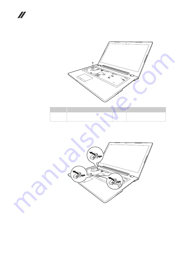
Figure 7. Removal steps of keyboard bezel (continued)
Remove the screw
.
Pull the touch pad connector, LED board and power button connector slot cover
upward as shown by arrows
, and detach the touch pad board cable, LED board
cable and power button cable from the touch pad board connector, LED board
connector and power button connector in the direction shown by arrows
.
When installing:
Make sure that the FPC connectors are attached firmly.
Step
Screw (quantity)
Color
Torque
M2 × 6 mm, Phillips-head,
nylokcoated (1)
Black
1.85+/-0.15 kgfcm
b
b
b
c
d
d
c
d
c
d
c


