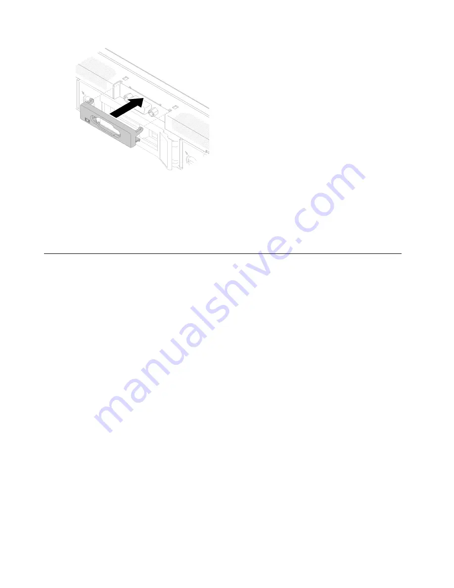
Figure 127. VGA cover installation
After you finish
1. Connect the VGA cable. See
“Front panel cable routing” on page 35
2. Install the top cover onto the server. See
“Install the top cover” on page 134
.
3. Complete the parts replacement. See
“Complete the parts replacement” on page 140
Complete the parts replacement
Use this information to complete the parts replacement.
To complete the parts replacement, do the following:
1. Ensure that all components have been reassembled correctly and that no tools or loose screws are left
inside your server.
2. Properly route and secure the cables in the server. Refer to the cable connecting and routing information
for each component.
3. If you have removed the server cover, reinstall it. See
“Install the top cover” on page 134
.
4. Reconnect external cables and power cords to the server.
Attention:
To avoid component damage, connect the power cords last.
5. Update the server configuration.
• Download and install the latest device drivers:
http://datacentersupport.lenovo.com
• Update the system firmware. See
.
• Update the UEFI configuration.
• Reconfigure the disk arrays if you have installed or removed a hot-swap drive or a RAID adapter. See
the Lenovo XClarity Provisioning Manager User Guide, which is available for download at:
140
ThinkSystem SR250 V2 Maintenance Manual
Содержание 7D7Q
Страница 1: ...ThinkSystem SR250 V2 Maintenance Manual Machine Types 7D7Q and 7D7R ...
Страница 8: ...vi ThinkSystem SR250 V2 Maintenance Manual ...
Страница 20: ...12 ThinkSystem SR250 V2 Maintenance Manual ...
Страница 35: ...2 5 inch drive model Figure 26 Server components 2 5 inch drive model Chapter 2 Server components 27 ...
Страница 42: ...34 ThinkSystem SR250 V2 Maintenance Manual ...
Страница 176: ...168 ThinkSystem SR250 V2 Maintenance Manual ...
Страница 180: ...172 ThinkSystem SR250 V2 Maintenance Manual ...
Страница 183: ......
Страница 184: ......


