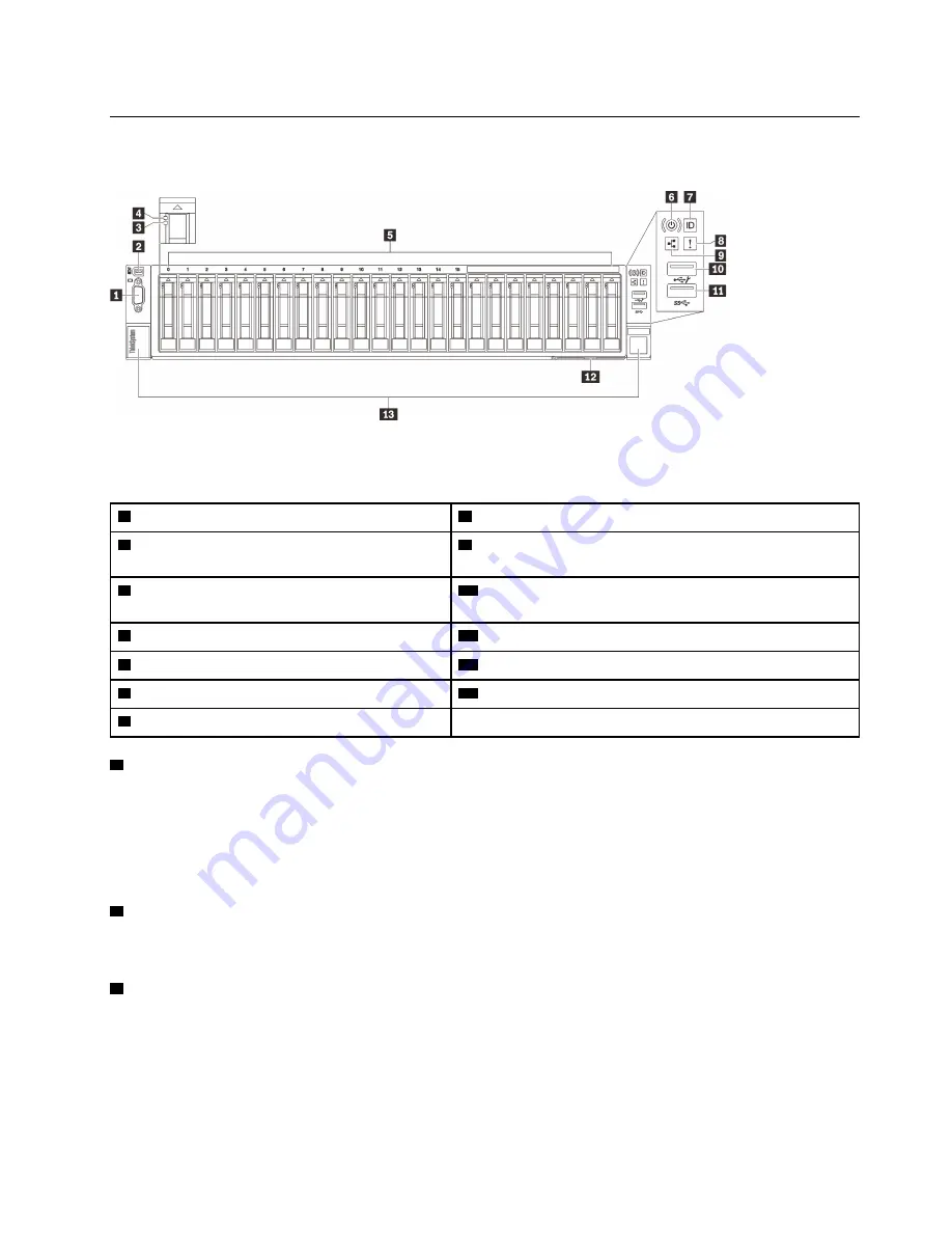
Front view
This section contains information about the controls, LEDs, and connectors on the front of the server.
Figure 5. Front view
Table 3. Components on the front view
1
“VGA connector (optional)” on page 15
8
“System error LED (yellow)” on page 16
2
“External LCD diagnostics handset
connector” on page 15
9
“Network activity LED (green)” on page 16
3
“Drive status LED (yellow)” on page 15
10
“USB 1” on page 16 (USB 2.0 with Lenovo XClarity
Controller management)
4
“Drive activity LED (green)” on page 16
11
“USB 2” on page 16 (USB 3.1)
5
“2.5-inch drive bays” on page 16
12
“Pull-out information tab” on page 16
6
“Power button/LED (green)” on page 16
13
“Rack release latches” on page 17
7
“Identification button/LED (blue)” on page 16
1
VGA connector (optional)
Connect a monitor to this connector.
Notes:
• When the optional front VGA connector is in use, the rear one will be disabled.
• The maximum video resolution is 1920 x 1200 at 60 Hz.
2
External LCD diagnostics handset connector
Connect the external LCD diagnostics handset here. See “External LCD diagnostics handset” on page 17 for
more details.
3
Drive status LED (yellow)
These LEDs indicate the following status:
• The LED is lit: the drive has failed.
• The LED is flashing slowly (once per second): the drive is being rebuilt.
• The LED is flashing rapidly (three times per second): the drive is being identified.
.
15
Содержание 7D31
Страница 1: ...ThinkSystem SR850 V2 Maintenance Manual Machine Types 7D31 and 7D32 ...
Страница 8: ...vi ThinkSystem SR850 V2 Maintenance Manual ...
Страница 52: ...44 ThinkSystem SR850 V2 Maintenance Manual ...
Страница 60: ... Three backplanes on page 57 52 ThinkSystem SR850 V2 Maintenance Manual ...
Страница 70: ...62 ThinkSystem SR850 V2 Maintenance Manual ...
Страница 71: ...Chapter 3 Internal cable routing 63 ...
Страница 78: ...70 ThinkSystem SR850 V2 Maintenance Manual ...
Страница 114: ...106 ThinkSystem SR850 V2 Maintenance Manual ...
Страница 227: ...Figure 129 Installing the air baffle to the system board Chapter 4 Hardware replacement procedures 219 ...
Страница 236: ...Figure 133 System board and expansion board LEDs 228 ThinkSystem SR850 V2 Maintenance Manual ...
Страница 258: ...250 ThinkSystem SR850 V2 Maintenance Manual ...
Страница 260: ...252 ThinkSystem SR850 V2 Maintenance Manual ...
Страница 264: ...256 ThinkSystem SR850 V2 Maintenance Manual ...
Страница 273: ......
Страница 274: ......


