background image

33 


Grounding cable 

This topic provides information about how to connect the grounding cable. Note that you need to prepare the 
grounding cable in advance before reading this topic. Lenovo does not provide the grounding cable.  

Grounding cable for the rack 

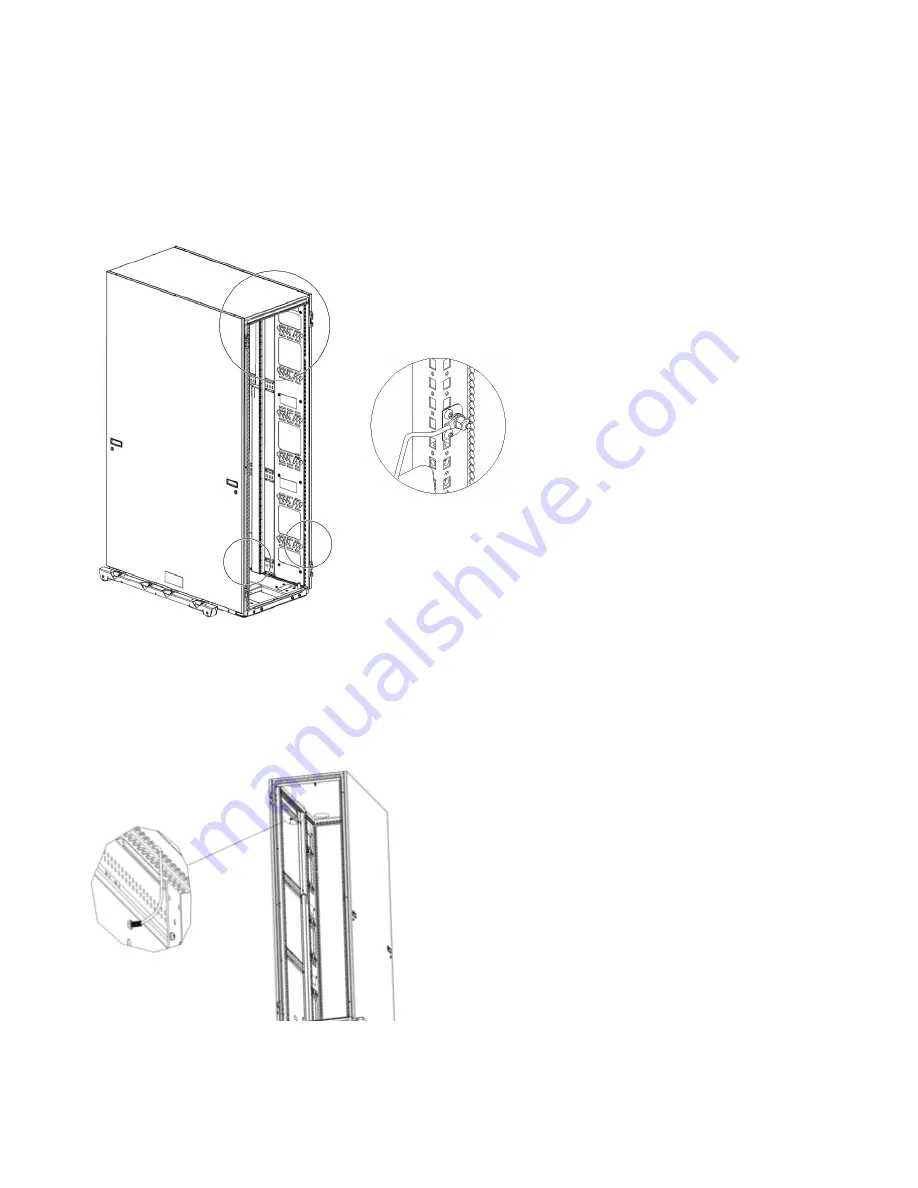
You need to connect a ground cable to the rear of the rack. There are no specific grounding pins on the rack 
frame. However, it is recommended that you refer to the following illustration to connect the ground cable to the 
top of the rear frames or the bottom of the rear vertical frames.  


Figure 22. Connecting the ground cable to the rear frames of the rack 


Grounding cable for the side panel 

It is optional to connect a ground cable to the side panel. To ground the side panel, connect one end of the 
ground cable to the grounding pin on the top of the side panel. Connect the other end of the ground cable to 
the top horizontal frame.  


Figure 23. Connecting the ground cable to the side panel 


Содержание 42U 1200 mm Deep Dynamic Rack

Страница 1: ...42U 1200 mm Deep Dynamic Rack 42U 1200 mm Deep Dynamic Expansion Rack Installation Guide ...

Страница 2: ...novo Documentation CD and the Important Notices and Warranty Information document that comes with the product Second Edition April 2020 Copyright Lenovo 2015 2020 LIMITED AND RESTRICTED RIGHTS NOTICE If data or software is delivered pursuant to a General Services Administration GSA contract use reproduction or disclosure is subject to restrictions set forth in Contract No GS 35F 05925 ...

Страница 3: ...25 Installation guidelines 25 Installing devices on the rack mounting flanges 26 Installing threaded rails 27 Installing cage nuts 27 Using the cage nut insertion tool 27 Using a flat blade screwdriver 28 Installing devices vertically in the rack 28 Chapter 4 Managing cables 29 Cable routing brackets 29 Using the cable access bar in the bottom of the rack 30 Using the cable access opening in the t...

Страница 4: ...iv Safety ...

Страница 5: ...ment in the Rack Safety Information document For example if a caution statement is labeled Statement 1 translations for that caution statement are in the Rack Safety Information document under Statement 1 Be sure to read all caution and danger statements in this document before you perform the procedures Read any additional safety information that comes with the server or optional device before yo...

Страница 6: ...d forseeable misuse conditions Statement 2 DANGER Always lower the leveling pads on the rack cabinet Always install stabilizer brackets on the rack cabinet Always install servers and optional devices starting from the bottom of the rack cabinet Always install the heaviest devices in the bottom of the rack cabinet Statement 3 DANGER Do not extend more than one sliding device at a time The maximum a...

Страница 7: ...ter or structural damage Disconnect the attached power cords telecommunications systems networks and modems before you open the device covers unless instructed otherwise in the installation and configuration procedures Connect and disconnect cables as described in the following table when installing moving or opening covers on this product or attached devices To Connect 1 Turn everything OFF 2 Fir...

Страница 8: ...ollow these general guidelines whenever you relocate a populated rack cabinet within a room or building Reduce the weight of the rack cabinet by removing equipment starting at the top of the rack cabinet When possible restore the rack cabinet to the configuration of the rack cabinet as you received it If this configuration is not known you must do the following Remove all devices in the 22U positi...

Страница 9: ...cation is required restore the rack cabinet to the configuration of the rack cabinet as you received it Pack the rack cabinet in the original packaging material or equivalent Also lower the leveling pads to raise the casters off of the pallet and strap the rack cabinet to the pallet Statement 12 CAUTION See the instructions in the rack documentation before you install devices remove devices or rel...

Страница 10: ...ne rack must be attached to the floor by a trained service technician according to your local building codes Place a fastener in each corner of the rack Each fastener must have a rated pull out force of at least 460 newtons ...

Страница 11: ...xi United Kingdom Notice to Customers This apparatus is approved under approval number NS G 1234 J 100003 for indirect connection to public telecommunication systems in the United Kingdom ...

Страница 12: ...umentation might be updated occasionally to include information about those features or technical updates might be available to provide additional information that is not included in the rack documentation Note Changes are made periodically to the Lenovo Web site Procedures for locating documentation might vary slightly from what is described in this document Notices and statements in this documen...

Страница 13: ...ding to your local building codes 2 The illustrations in this document might differ slightly from your hardware Statement 1 CAUTION To ensure safety all configurations of the rack cabinet must be certified by a nationally recognized testing laboratory in order to verify compliance with country specific safety regulations This process ensures that the end product remains safe for the operator and s...

Страница 14: ...ithout outriggers 2000 mm x 605 mm x 1200 mm 78 7 in x 23 8 in x 47 2 in 9360 4PX 42U deep dynamic rack cabinet with outriggers 2000 mm x 745 mm x 1200 mm 78 7 in x 29 3 in x 47 2 in 9360 4EX 42U deep dynamic expansion rack cabinet without outriggers 2000 mm x 600 mm x 1200 mm 78 7 in x 23 8 in x 47 2 in 9360 4EX 42U deep dynamic expansion rack cabinet with outriggers 2000 mm x 745 mm x 1200 mm 78...

Страница 15: ...ove the outriggers use the M5 hex wrench that comes in the hardware kit to remove the four bolts that attach each outrigger to the rack cabinet Keep the outriggers and bolts for future use if you have to move the rack Note Before you attach an expansion rack to a standard rack or another expansion rack you must remove the outriggers from the racks so that the racks fit together correctly Install t...

Страница 16: ...ower the leveling pads and install the front stabilizer complete the following steps 1 Use the smaller end of the open end wrench that comes with the hardware kit to lower each of the four leveling pads just enough so that they touch the floor The rack casters support the weight of the rack cabinet The pads prevent the rack from rolling Figure 4 Lowering the leveling pads 2 Hand tighten the thumbs...

Страница 17: ...crews and hex wrench that come with the hardware kit Stabilizer bracket Figure 6 Installing the front stabilizer c Remove the side covers see Removing and installing the upper side covers for instructions d Attach the side stabilizer brackets to the center cage nut on each side of the rack with the hex bolts and washers see Figure 7 The stabilizer brackets bolts and washers come in the hardware ki...

Страница 18: ... brackets see Figure 7 and reinstall the side covers Removing and installing the upper side covers The standard rack comes with the upper side covers installed Remove the side covers from the rack before you install or remove optional devices To remove the upper side covers from a standard rack complete the following steps 1 Unlock both button locks on a side cover Side cover Handle Button lock ...

Страница 19: ...reverse the removal procedure Lock each side cover to secure it to the rack cabinet Side cover Handle Button lock Figure 9 Installing an upper side cover Installing and removing the lower side panels Two lower side panels and attaching hardware come with the standard rack cabinet To attach a lower side panel to an upper side cover press the five plastic pins through the holes on the bottom of the ...

Страница 20: ... that you remove the lower side panels before you install the outriggers Removing and installing rack cabinet doors All deep dynamic racks come with front and rear doors installed Remove the rack doors when you install and remove devices in the rack if part of the rack is obstructed by the door as you install devices Removing and installing a front door To remove a front door from the rack cabinet...

Страница 21: ... down to the closed position Removing and installing rear doors To remove the rear doors from the rack cabinet complete the following steps 1 Unlock and open the right side door Figure 12 Opening and removing the rear doors 2 Hold the door firmly with one hand then lift both hinge pins on the inside of the door until they lock in the open position This releases the door from the hinges 3 Grasp the...

Страница 22: ...site direction complete the following steps 1 Remove the door according to Removing and installing a front door 2 Use a hex wrench to remove the top and bottom hinges from the rack cabinet then install the hinges on the other side of the rack Note There are extra screws in the hardware kit in case you drop one into the rack channel Figure 13 Moving the door hinges and front door latch 3 Remove the...

Страница 23: ...f the door Figure 15 Moving the Lenovo logo Attaching racks in a suite Expansion racks come with all the hardware that is required for you to attach racks together and form a suite A box wrench hex wrench and screws come with the expansion rack hardware kit You need one standard rack to form a suite You do not have to remove the doors to attach the racks together ...

Страница 24: ...d rear vertical edges of the expansion rack to prevent the two racks from rubbing against each other 3 Insert an attachment pin that comes with the expansion rack through the top slot on the front of the standard and expansion racks as shown in Figure 16 The slot is behind the top hinge 4 Hold the attachment pin in place with the box wrench and use the hex wrench to tighten a screw on each side of...

Страница 25: ...t Statement 3 Do not extend more than one sliding device at a time The maximum allowable weight for devices on slide rails is 80 kg 176 lb Do not install sliding devices that exceed this weight Statement 4 DANGER Electrical current from power telephone and communication cables is hazardous To avoid a shock hazard Do not connect or disconnect any cables or perform installation maintenance or reconf...

Страница 26: ...tement 5 18 kg 39 7 lb 32 kg 70 5 lb 55 kg 121 2 lb CAUTION Use safe practices when lifting Statement 6 CAUTION Do not place any object on top of a rack mounted device unless that rack mounted device is intended for use as a shelf Always install the heaviest devices in the bottom of the rack For information about optional compatible devices that you can install in the rack go to the ServerProven W...

Страница 27: ...mounting flanges with either the cage nut insertion tool or a flat blade screwdriver The cage nut insertion tool comes with the rack and some optional devices Using the cage nut insertion tool Complete the following steps to install a cage nut with the cage nut insertion tool Cage nut Cage nut insertion tool Rack mounting flange Figure 17 Installing cage nuts with the cage nut insertion tool 1 Det...

Страница 28: ...mpressed push the edge of the cage nut fully into the hole from the inside of the rack mounting flange 4 Release the screwdriver pressure on the clip to lock the cage nut into place Installing devices vertically in the rack The racks come with space on the sides that can be used to vertically mount power distribution units PDUs and console switches The racks come with six locations three on each s...

Страница 29: ...ied limits Label all cables so that they are clearly distinguishable from each other When installing devices mounted on slide rails such as servers observe the following precautions Run the cables neatly along equipment cable management arms and secure the cables to the arms using provided cable straps Leave enough extra cable so that the device can fully extend without straining the cables Secure...

Страница 30: ...ccess bar in the bottom of the rack Complete the following steps to route external cables through the opening provided in the bottom rear of the racks 1 Remove the four screws and washers that attach the cable access bar to the rack cabinet as shown in the following illustration ...

Страница 31: ... using the cable access bar 2 Route the cables through the opening 3 Reattach the cable access bar to the rack cabinet with the four screws and washers that you removed in step 1 Make sure that you do not pinch or cut any cables ...

Страница 32: ... the rack 2 Route the cables through the opening 3 Slide the cable access panel toward the back of the rack Make sure that you do not pinch or cut any cables 4 Tighten the two wing nuts Complete the following steps to route external cables through the two round cable access openings in the top front of the standard or expansion rack 1 Use a flat blade screwdriver to pry the round cable access cove...

Страница 33: ...owever it is recommended that you refer to the following illustration to connect the ground cable to the top of the rear frames or the bottom of the rear vertical frames Figure 22 Connecting the ground cable to the rear frames of the rack Grounding cable for the side panel It is optional to connect a ground cable to the side panel To ground the side panel connect one end of the ground cable to the...

Страница 34: ... cable to the rear door To ground the rear door connect one end of the ground cable to the grounding pin on the bottom of the rear door Connect the other end of the ground cable to the bottom of the rear vertical frame Figure 24 Connecting the ground cable to the rear door ...

Страница 35: ...35 Chapter 5 Moving a rack Before you move the rack cabinet to another location read the important guidelines in this chapter When you move a rack cabinet observe the following safety guidelines ...

Страница 36: ...f the rack cabinet as you received it If this configuration is not known you must do the following Remove all devices in the 22U position and above Ensure that the heaviest devices are installed in the bottom of the rack cabinet Ensure that there are no empty U levels between devices installed in the rack cabinet below the 22U level If the rack cabinet you are relocating is part of a suite of rack...

Страница 37: ...ople are required to move the rack If the rack cabinet weight is between 142 and 227 kg between 313 and 500 lb three or four people are required to move the rack If the rack cabinet weight is greater than 227 kg 500 lb professional movers are required to move the rack 4 Install the outriggers on both sides of the rack cabinet DANGER Always relocate the rack cabinet with the outriggers installed Ke...

Страница 38: ...38 5 Carefully move the rack cabinet to the new location by using the safety guidelines in this chapter ...

Страница 39: ...s are of three types Tier 1 customer replaceable unit CRU Replacement of Tier 1 CRUs is your responsibility If Lenovo installs a Tier 1 CRU at your request you will be charged for the installation Tier 2 customer replaceable unit You may install a Tier 2 CRU yourself or request Lenovo to install it at no additional charge under the type of warranty service that is designated for your server Field ...

Страница 40: ...Side cover 69Y6045 4 Lower side panel 69Y6046 5 Cable access bar 46M5278 6 Hardware and tool kit includes tools screws washers cage nuts and fasteners 46M5263 7 Outrigger side stabilizer 69Y6049 8 Swivel caster rear 46M5260 9 Fixed caster front 46M5261 10 Adjustable foot 46M5262 11 Front stabilizer 39M6739 12 Front door 16R1485 13 Keys door and side cover 16R1497 14 Latch door 16R1496 15 Cover top...

Страница 41: ...your Lenovo product The Lenovo Warranty terms and conditions state that you the owner of the Lenovo product are responsible for maintaining and updating all software and firmware for the product unless it is covered by an additional maintenance contract Your service technician will request that you upgrade your software and firmware if the problem has a documented solution within a software upgrad...

Страница 42: ...d or changes in the product s and or the program s described in this publication at any time without notice The products described in this document are not intended for use in implantation or other life support applications where malfunction may result in injury or death to persons The information contained in this document does not affect or change Lenovo product specifications or warranties Noth...

Отзывы: