


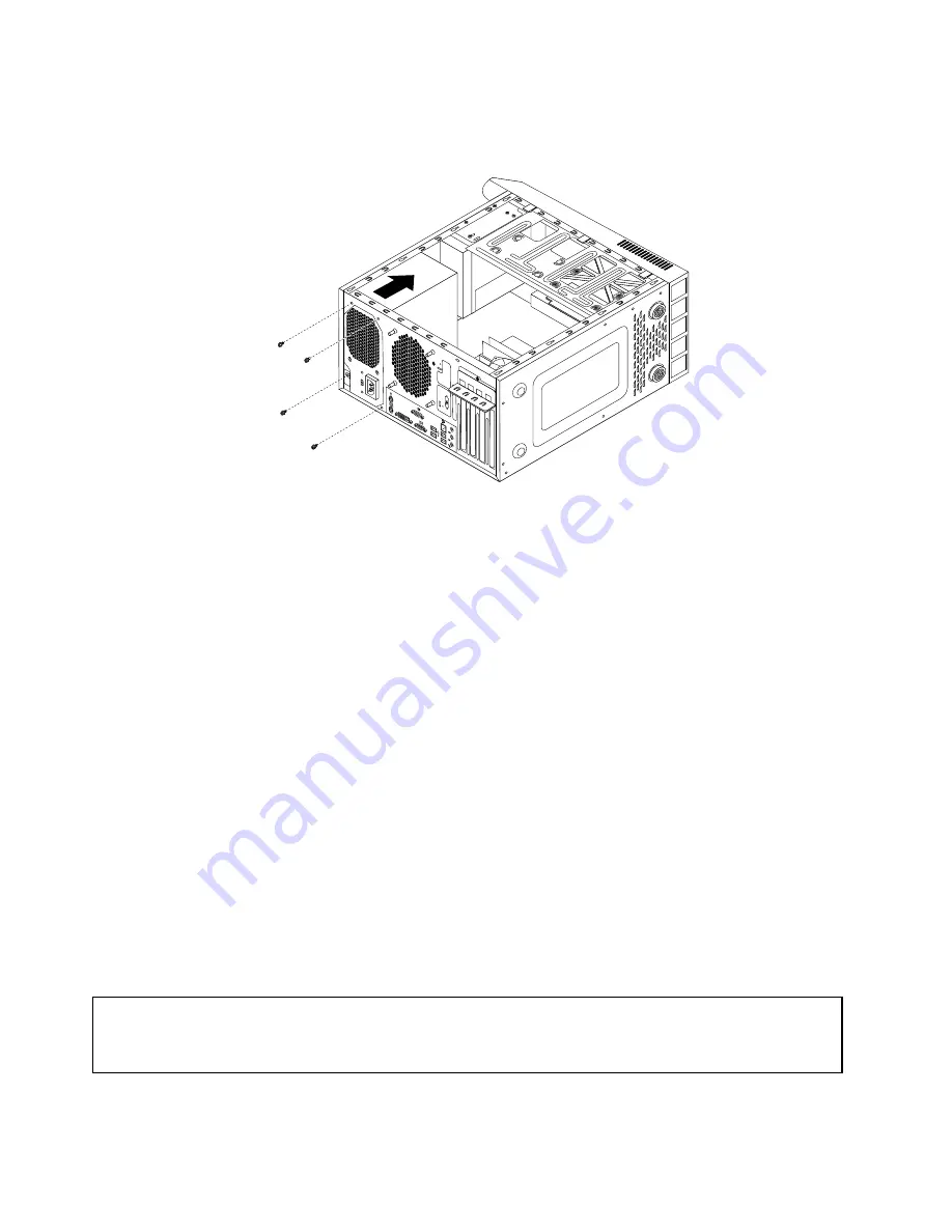
4. Lay the computer on its side and remove the four screws at the rear of the chassis that secure the
power supply assembly.
Figure 21. Removing the screws for the power supply assembly
5. Slide the power supply assembly to the front of the computer and then lift it out of the chassis.
6. Make sure that the new power supply assembly is the correct replacement. Some power supply
assemblies automatically sense the voltage, some power supply assemblies are voltage specific, and
some power supply assemblies have a voltage-selection switch. If your power supply assembly has
a voltage-selection switch, make sure that you set the voltage-selection switch to match the voltage
available at your electrical outlet. If necessary, use a ballpoint pen to slide the voltage-selection switch
to the correct position.
• If the voltage supply range in your local country or region is 100–127 V ac, set the voltage-selection
switch to 115 V.
• If the voltage supply range in your local country or region is 200–240 V ac, set the voltage-selection
switch to 230 V.
7. Install the new power supply assembly into the chassis so that the screw holes in the power supply
assembly align with those in the chassis.
8. Install and tighten the four screws to secure the power supply assembly.
Note:
Use only screws provided by Lenovo.
9. Reconnect the power supply assembly cables to the system board and each of the drives.
10. Secure the power supply assembly cables with the cable clips and ties in the chassis.
11. To complete the installation or replacement, go to “Completing the parts replacement” on page 104.
Replacing the microprocessor
Attention:
Do not open your computer or attempt any repair before reading and understanding the “Important safety information”
in the
ThinkCentre User Guide
. To obtain a copy of the
ThinkCentre User Guide
, go to:
http://www.lenovo.com/ThinkCentreUserGuides
This section provides instructions on how to replace the microprocessor.
94
ThinkCentre Hardware Maintenance Manual
Содержание 3133A2U
Страница 6: ...2 ThinkCentre Hardware Maintenance Manual ...
Страница 13: ...Chapter 2 Safety information 9 ...
Страница 14: ... 18 kg 37 lb 32 kg 70 5 lb 55 kg 121 2 lb 10 ThinkCentre Hardware Maintenance Manual ...
Страница 18: ...14 ThinkCentre Hardware Maintenance Manual ...
Страница 19: ...1 2 Chapter 2 Safety information 15 ...
Страница 20: ...1 2 16 ThinkCentre Hardware Maintenance Manual ...
Страница 26: ...22 ThinkCentre Hardware Maintenance Manual ...
Страница 27: ...1 2 Chapter 2 Safety information 23 ...
Страница 31: ...Chapter 2 Safety information 27 ...
Страница 32: ...1 2 28 ThinkCentre Hardware Maintenance Manual ...
Страница 36: ...32 ThinkCentre Hardware Maintenance Manual ...
Страница 40: ...36 ThinkCentre Hardware Maintenance Manual ...
Страница 52: ...48 ThinkCentre Hardware Maintenance Manual ...
Страница 76: ...72 ThinkCentre Hardware Maintenance Manual ...
Страница 110: ...106 ThinkCentre Hardware Maintenance Manual ...
Страница 346: ...342 ThinkCentre Hardware Maintenance Manual ...
Страница 351: ......
Страница 352: ...Part Number 0B02865 Printed in USA 1P P N 0B02865 0B02865 ...