


Hazardous voltage, current, and energy levels are present inside any component that has this label
attached. There are no serviceable parts inside these components. If you suspect a problem with
one of these parts, contact a service technician.
To replace the power supply assembly, do the following:
1. Turn off the computer and disconnect all power cords from electrical outlets.
2. Remove the computer cover. See “Removing the computer cover” on page 35.
3. Disconnect the power supply assembly cables from all drives and from the 24-pin power connector and
4-pin power connector on the system board. See “Locating parts on the system board” on page 13.
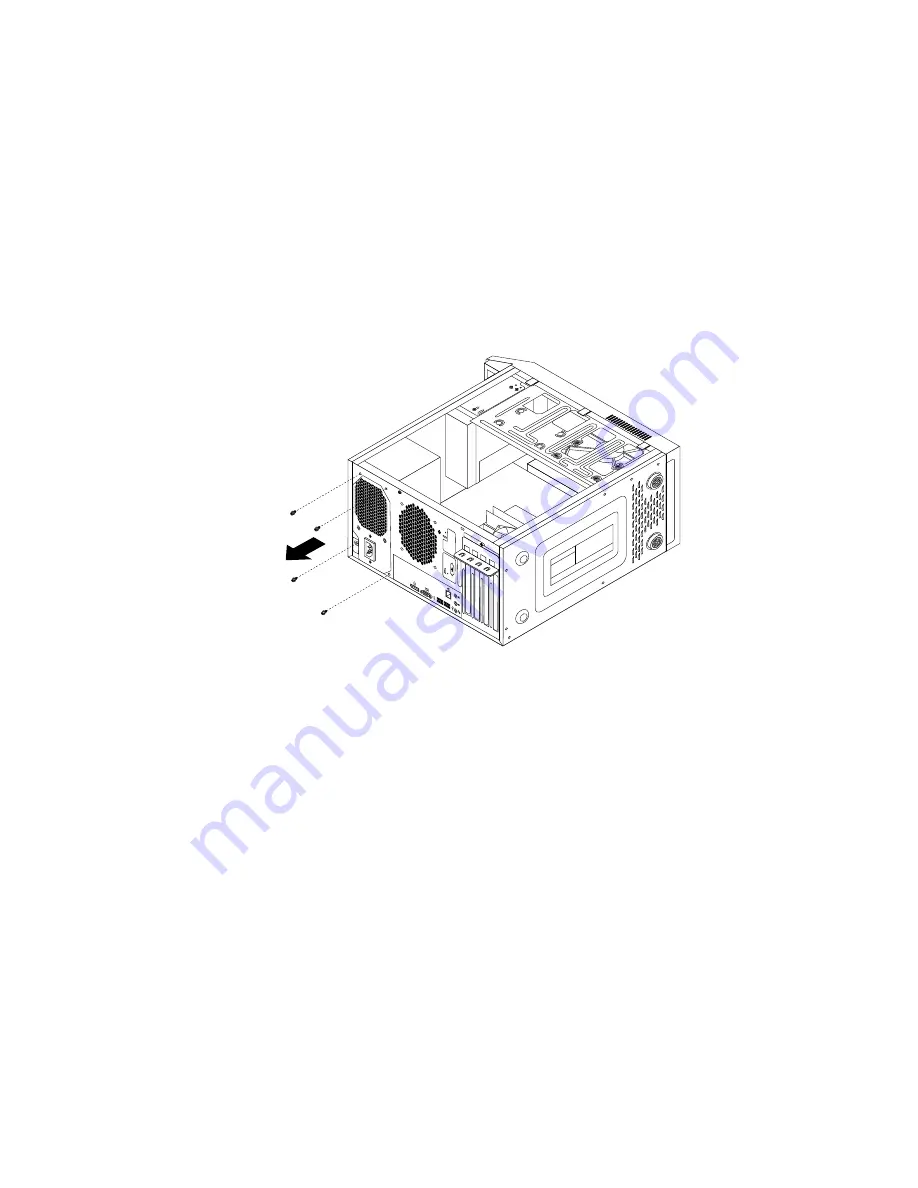
4. Lay the computer on its side and remove the four screws at the rear of the chassis that secure the
power supply assembly.
3
4
5
6
Figure 26. Removing the screws for the power supply assembly
5. Slide the power supply assembly to the front of the computer and then lift it out of the chassis.
6. Make sure that the new power supply assembly is the correct replacement. Some power supply
assemblies automatically sense the voltage, some power supply assemblies are voltage specific, and
some power supply assemblies have a voltage-selection switch. If your power supply assembly has
a voltage-selection switch, make sure that you set the voltage-selection switch to match the voltage
available at your electrical outlet. If necessary, use a ballpoint pen to slide the voltage-selection switch
to the correct position.
• If the voltage supply range in your local country or region is 100–127 V ac, set the voltage-selection
switch to 115 V.
• If the voltage supply range in your local country or region is 200–240 V ac, set the voltage-selection
switch to 230 V.
7. Install the new power supply assembly into the chassis so that the screw holes in the power supply
assembly align with those in the chassis.
8. Install and tighten the four screws to secure the power supply assembly.
Note:
Use only screws provided by Lenovo.
9. Reconnect the power supply assembly cables to the system board and each of the drives.
10. Secure the power supply assembly cables with the cable clips and ties in the chassis.
Installing or replacing hardware
49
Содержание 10AS
Страница 1: ...ThinkCentre E73 User Guide Machine Types 10AS 10AV 10DR and 10DS ...
Страница 6: ...iv ThinkCentre E73 User Guide ...
Страница 12: ...x ThinkCentre E73 User Guide ...
Страница 28: ...16 ThinkCentre E73 User Guide ...
Страница 80: ...68 ThinkCentre E73 User Guide ...
Страница 94: ...82 ThinkCentre E73 User Guide ...
Страница 102: ...90 ThinkCentre E73 User Guide ...
Страница 126: ...114 ThinkCentre E73 User Guide ...
Страница 136: ...124 ThinkCentre E73 User Guide ...
Страница 138: ...Ukraine RoHS India RoHS RoHS compliant as per E Waste Management Handling Rules 2011 126 ThinkCentre E73 User Guide ...
Страница 139: ...Appendix E China Energy Label Copyright Lenovo 2013 2014 127 ...
Страница 140: ...128 ThinkCentre E73 User Guide ...
Страница 142: ...130 ThinkCentre E73 User Guide ...
Страница 146: ...134 ThinkCentre E73 User Guide ...
Страница 147: ......
Страница 148: ......


