background image

13

Indoor Unit

2~3-15/16 in.

8 in.

2~3-15/16 in.

2~3-15/16 in.

MAIN DRAIN

INDIVIDUAL DRAIN OUTLET FROM EACH INDOOR UNIT

(Must be connected to internal pump and must be routed to

main drain as shown.)

ti

n

U

 r

o

o

d

n

I

ti

n

U

 r

o

o

d

n

I

(Sloped at 1/4” per foot (6 mm per 305 mm) AWAY 

from unit and should be supported as needed to prevent sagging.)

8 in.

8 in.

Max. 28 in.

Max. 28 in.

Max. 28 in.

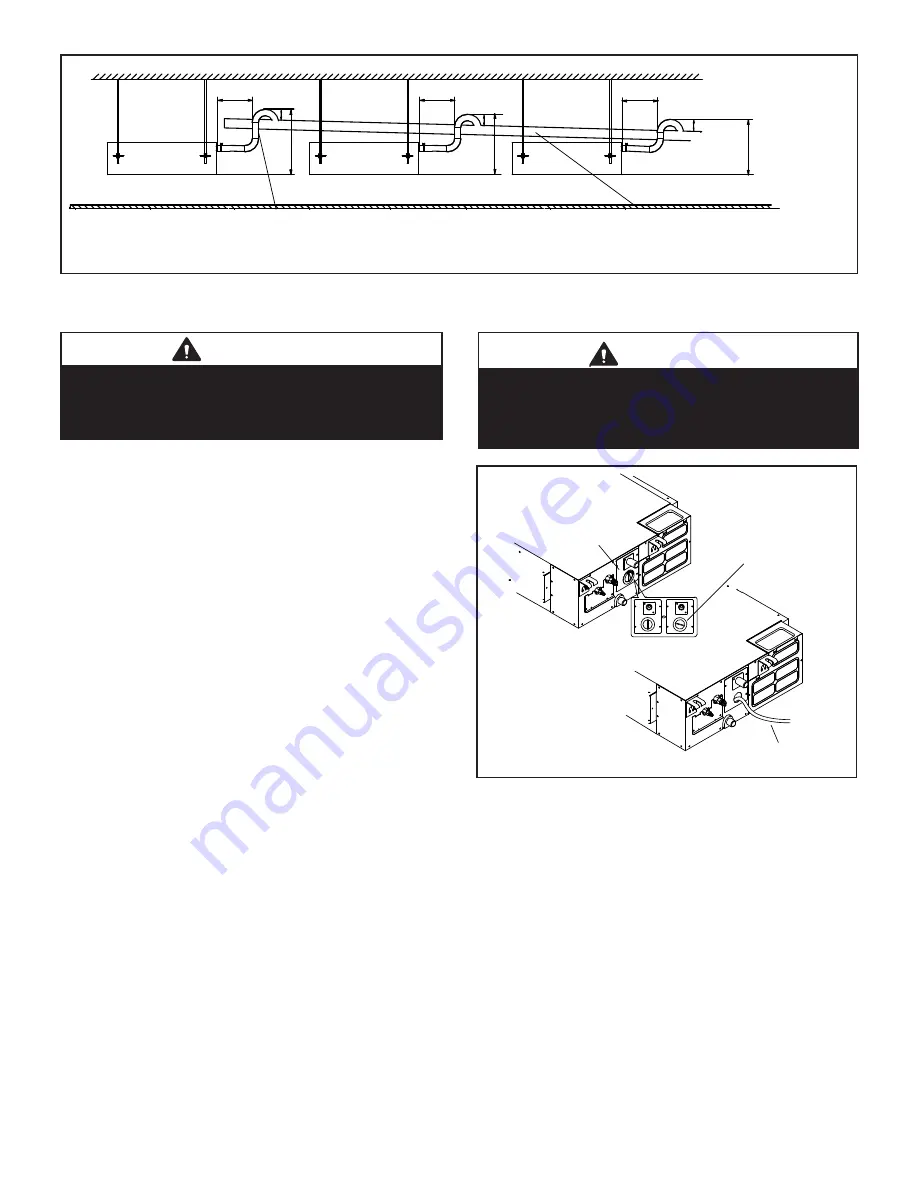
Figure 19. Condensate Drain with Lift Pump  

Multiple Indoor Units

7.  After system installation is complete, the 

condensate drain line must be checked for leaks 

and the condensate pumps must be checked to 

ensure proper operation. This check is part of the 

commissioning sequence. 

Turn the condensate 

drain pan test cover latch counterclockwise to open 

the cover and access the drain pan. See Figure 20. 

Funnel enough water to engage the pump into the 

drain pan through a flexible tube.

8.  Operate the system in the cooling mode. If the 

internal pump is being used, ensure that the pump is 

operating and the water in the pan is draining freely. 

If the internal pump is not being used, pour the water 

into the drain pan and confirm that it has flowed freely 

out of the pan and out of the drain termination. If a 

leak is found, shut down power to the unit at once and 

do not restore power to the unit until the problem has 

been resolved.

DRAIN PAN

TEST COVER

FUNNEL WATER INTO

PAN THROUGH TUBE

FOR TEST

COVER LATCH

(Turn latch

counterclockwise

to unlock)

CLOSEDOPEN

CLOSE

D OPEN

Figure 20. Condensate Drain Test

9.  Return the test cover and turn the latch clockwise to 

re-lock it.

 IMPORTANT

When using a gravity drain instead of the factory-

installed lift pump.  

Disconnect the factory-installed lift pump, CN 13. See 

unit wiring diagrams for location of CN 13.

 IMPORTANT

Drain should have a slope of at least ¼ inch per foot and 

should be approved corrosion-resistant pipe. You must 

confirm operation of every drain and pump in the system 

as part of the commissioning procedure.

Содержание VRF VMDB Series

Страница 1: ...sed professional HVAC installer service agency or the gas supplier Failure to follow safety warnings and these instruc tions exactly could result in property damage dan gerous operation serious injury...

Страница 2: ...ce a fuse with a fuse of a different rating Do not use a jumper wire to replace a fuse Do not insert your hands tools or any other item into the air intake or air outlet at either the indoor or outdoo...

Страница 3: ...UNIT REAR OF UNIT SECTION A A SECTION D D SECTION B B SECTION C C SECTION B B SECTION C C SECTION A A SECTION D D TOP OF UNIT NOTE Unit orientation reversed to show alternative filter location and re...

Страница 4: ...2 13 1 25 1 3 4 44 1 7 8 48 CONDENSATE LIFT PUMP Size A B C D E F G H J in mm in mm in mm in mm in mm in mm in mm in mm in mm 012 36 1 4 921 10 5 8 270 25 3 8 645 22 1 2 572 39 3 4 1010 2 5 8 67 28 71...

Страница 5: ...in any form Minimum clearances must be observed at all times NOTE Horizontal installation only 20 508 mm Minimum Service Clearance 24 610 mm Air Flow 24 610 mm Minimum Service Clearance TOP VIEW DUCT...

Страница 6: ...te support for the weight of the duct system Duct system must not be supported by the indoor unit It is recommended that you use flexible joints canvas at the point where the duct connects to the unit...

Страница 7: ...d then a nut onto each rod below each suspension bracket Use the leveling nut beneath suspension bracket to adjust the unit to the correct height Remove the electrical tape holding the upper washers a...

Страница 8: ...es the filter retaining bracket and slide the bracket away from the unit 3 Grasp the filter removal tab and slide the filter out Figure 7 Loosen Filter Retaining Bracket Filter removal tab Figure 8 Sl...

Страница 9: ...pplied foam insulating tape to the return air opening on the bottom of the unit See Figure 11 Figure 11 Apply Foam Insulating Tape Field supplied foam insulating tape 5 Use the existing screws to re i...

Страница 10: ...PORTANT Support ALL piping within 12 in 305 mm of any mechanical fitting such as a flared connection WARNING Danger of fire Bleeding the refrigerant charge from only the high side may result in pressu...

Страница 11: ...on conditions 4 All refrigerant piping shall be free of defects debris and oil 5 Connect the liquid and gas lines to the evaporator coil 6 Always use an appropriate heat absorption compound to protect...

Страница 12: ...rnal drain pump Suspension Rods Drain line Structural Ceiling 3 ft 1 m Support straps NOTE Drain line should be sloped 1 4 inch per foot 18 mm per m AWAY from unit and should be supported as needed to...

Страница 13: ...system in the cooling mode If the internal pump is being used ensure that the pump is operating and the water in the pan is draining freely If the internal pump is not being used pour the water into t...

Страница 14: ...ions Clamp cables securely and make sure that connections are tight to avoid strain on wiring Insecure wiring connections may result in equipment failure and risk of fire Wiring must be installed so t...

Страница 15: ...gure 21 Typical Power Wiring Diagram VRF Heat Recovery System Shown L2 L3 L1 L2 L1 208 230V 3Ph 60Hz or 460V 3Ph 60Hz Power supply 208 230V 1Ph 60Hz Power supply Mode Selection Box Indoor unit Indoor...

Страница 16: ...PQ PQ H1 H2 H1 H2 H1 H2 Outdoor Unit Communication Terminal Block P Q H1 H2 X Y O A K1 K2 MS Box Communication Terminal Block P Q Indoor Unit Communication Terminal Block HA HB 12V COM P Q Ground drai...

Страница 17: ...ler Signal transmission wire X2M 0 58 0 72 Terminal base of power supply X1M 0 87 1 06 Grounding terminal M4 1 06 1 43 PQ PQ Outdoor unit mainunit Outdoor unit sub1unit Outdoor unit sub2 unit Install...

Страница 18: ...E F8 No address Outdoor unit fault Water level alarm Emergency stop Remote OFF E6 DC fan motor error E7 EEPROM failure error 5V GND 12V ONLY USED FOR TESTING CN30 RED BLACK HA HB 12V COM Q P Magnet Ri...

Страница 19: ...6 Locate the return air thermistor to the conditioned area of which the indoor unit serves Figure 29 Sensor Thermistor Relocate the unit return air sensing from inside the unit to a location within th...

Страница 20: ...K WHITE RED XS4 XS3 XS2 XS1 XS6 XP7 XS7 CN12 NOTE 1 Refer to manual for communication wiring 2 Please use the 2 conductor shielded twisted cable for communication NOTE Component in dash line is option...

Страница 21: ...l indoor temperature T1 6 The middle coil temperature T2 7 The coil inlet temperature T2A 8 The coil outlet temperature T2B 9 The actual superheat temperature 10 The actual subcool temperature 11 Erro...

Страница 22: ...it Fault EE High Water Alarm A0 Emergency stop D8 Remote off U4 MS self inspection error F8 MS error Table 8 Fault Code Display on Controller Error Code Description F0 Communication Address error betw...

Страница 23: ...23...

Страница 24: ...m Reference and adhere to the latest revision of the installation instructions Installation instructions can be downloaded from www lennoxvrf com www lennoxcommercial com www lennoxpros com and the Le...

Отзывы: