background image

Multi-VRF Centralized Controller Operation Manual 

13 

No. 

Name 

Instructions 


Error status 

Error icon will be displayed if indoor unit is malfunctioning. 


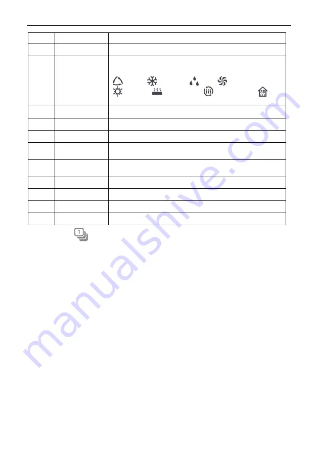
Operation mode


When indoor unit is on, the current operation mode will be 
displayed: 

  Auto     

  Cooling     

  Dry   

  Fan


  Heating   

  Floor heating


  Space heating


3D 

heating


Shield status


This icon will be displayed when indoor unit is in shield status.


IDU Sort 

Press the button to enter into the idu sort page. 


All Off button 

Press this button to turn off all air conditioning equipment. 


Right page 

button 

Press this button to show the next page idu list. 


Current page 

The total pages of the controlled indoor unit and the current 
page. 


Left page button 

Press this button to show the previous page idu list. 


All On button


Press this button to turn on all air conditioning equipment.


IDU icon 

Display the icon of the indoor unit. 


IDU name 

Display the name of the indoor unit. 

Press the 

  button to enter the IDU sort page. 

Select one indoor unit , press the left or right button at the bottom of the screen to 

switch the display of the indoor units. 
 

3.3 Single Unit Control 

On the indoor unit control page or group page, press the icon of indoor unit to enter 

the single unit control. 

Press the icon of indoor unit for 5 seconds to pop up the name set of the selected 

indoor unit. 

Parameters  of  single  unit  control  include  parameters  of  general  control  and 

advanced control. 

3.3.1 General Control Parameters 

Содержание VESZC1

Страница 1: ...al Commercial Air Conditioners Model Multi VRF Centralized Controller VESZC1 D Thank you for selecting LENNOX air conditioners Please read this manual carefully before operation and keep it for furthe...

Страница 2: ...zed controller Never operate the centralized controller with wet hands Never scratch the screen of centralized controller by hard or sharp objects If the centralized controller is connected with the o...

Страница 3: ...AND WORKING INSTRUCTIONS 8 2 1 MAIN PAGE DISPLAY AND BUTTONS 9 2 2 GENERAL BUTTONS 9 2 3 BUTTONS WORKING INSTRUCTIONS 10 3 FUNCTIONS DESCRIPTION 12 3 1 HELP INFO 12 3 2 INDOOR UNIT 12 3 3 SINGLE UNIT...

Страница 4: ...een Self tapping screw ST4 2 9 5 MC used to secure the rear cover of controller Rear cover of controller Rubber band QTY 1 4 1 6 No Name Screw M4 12 used to secure earthing wire Screw ST4 2 16 FA used...

Страница 5: ...6 L 1000m L 3280 5 6feet If cord size is 2 1mm2 2 AWG16 communica tion cord can be stretched longer But the total length can t exceed 1500m 4921 1 4feet Outdoor network L 250 L 820 1 5feet Total lengt...

Страница 6: ...oltage 100 240 VAC Frequency range 50 60Hz Select power cord according to the following table Never use the power cord that is not in compliance with instructions of this manual Cord type Cord standar...

Страница 7: ...Method 2 Connect with outdoor network Fig 1 5 Centralized Controller Connected with Outdoor Network Method 3 Connect with heat recollection mode converter Network Fig 1 6 Centralized Controller Conne...

Страница 8: ...t the G1 and G2 ports d The centralized control address DIP switch SA2_Addr CC indicates the centralized control address required when different refrigerating systems are controlled in a centralized m...

Страница 9: ...1 0 7 1 1 1 0 8 0 0 0 1 9 1 0 0 1 10 0 1 0 1 11 1 1 0 1 12 0 0 1 1 13 1 0 1 1 14 0 1 1 1 15 1 1 1 1 16 e The centralized control address DIP switch SA2_Addr CC cannot be the same between different ref...

Страница 10: ...the centralized controller is installed on wall dig a hole that is the size of 180mm 107mm 62mm and peg 4 wooden or plastic plugs on the wall according to fig 1 8 2 In case that the centralized contr...

Страница 11: ...connect the ground wire to position on the electric box rear cover Secure it with screw M4 12 8 In step locate the controller s rear cover onto the electric box rear cover with screw ST4 2 9 5 TC 9 I...

Страница 12: ...this button to enter schedule page 6 Group button Press this button to enter group page 7 All Control button Press this button to enter All Control page 8 Indoor Unit button Press this button to ente...

Страница 13: ...ress this button to move the selected IDU forward one place Backward Shift On the IDU sort page Press this button to move the selected IDU backward one place Info Press this button to enter Info page...

Страница 14: ...sleep button can turn off the sleep function 3 Sliding Sliding up down to slide the group and setting page up down 4 Sliding bar Press and hold the sliding bar to drag up down or left right and to adj...

Страница 15: ...1 Page of Indoor Unit No Name Instructions IDU display Display in separate page the list of indoor units that are controlled by the centralized controller IDU icon Press the button to enter the page o...

Страница 16: ...of the controlled indoor unit and the current page Left page button Press this button to show the previous page idu list All On button Press this button to turn on all air conditioning equipment IDU...

Страница 17: ...cted Note Auto mode can only be set in the master indoor unit Heat recollection system have no master indoor unit When the indoor unit of the same branch is connected into one indoor unit the auto mod...

Страница 18: ...indoor unit fails to function well the will turn red then press the button to view the information of malfunctions 3 3 2 Advanced Control Parameters Press Advance Button to enter the advance page Pres...

Страница 19: ...ent for different unit 3 4 All Control Function On the homepage press to enter into the page of All Control Fig 3 4 All Control Page All Control Function can operate all indoor units as below 1 ON OFF...

Страница 20: ...or up down swing button to turn on or turn off swing function 6 Send order Press button to send out the All Control order 3 5 Group Control On the homepage press to enter into the page of group functi...

Страница 21: ...he page of group editing Use can set the group name and add indoor units to the group Press to save the setting Note 1 set of indoor unit can be set in up to 5 groups 3 IDU sort Press the button to en...

Страница 22: ...Multi VRF Centralized Controller Operation Manual 19 Fig 3 6 Page of Schedule Fig 3 7 Page of Schedule Editing 1 Open the schedule Press the zone button to open or close the schedule...

Страница 23: ...the same time In this case unit will work according to the schedule setting that is previously energized 3 Repeat schedule Press Repeat Setting button to enter the setting page User can set the schedu...

Страница 24: ...ing page Press the Local Setting button to switch to the setting options of the current unit Select the needed option at the left side column Sliding up and down can turn over the page Set the corresp...

Страница 25: ...sleep mode use can wake it up by touching any part of the touch screen or the touch button at the right bottom of the screen 5 Brightness Pressing or dragging the sliding bar can adjust the backlight...

Страница 26: ...ineering No of indoor unit icon and then press to save it will display the registered indoor unit in the indoor unit page Notes There are 255 sets of indoor units can be registered at most 2 Name Icon...

Страница 27: ...Time management page Selectting the ODU s system number or IDU s engineering No then user can view the ODU or IDU continuous time and total time 3 9 About On the home page press to enter into setting...

Страница 28: ...s at 1 305 718 2901 lennoxglobalhvac lennoxintl com C 2017 Lennox Industries Inc For a complete list of the registered and common law trademarks owned by Lennox Industries Inc please visit www lennoxg...

Отзывы: