background image

Page 8

Refrigerant Charge and Check

TPA units have a factory holding charge of 1 pound of
HFC-410A.  Additional refrigerant will need to be added
during installation (table 2).

Table 2. Adding Refrigerant


Models

25 Feet

1

(pounds)

Liquid

Line

Diameter

(inches)

Vapor

Line

Diameter

(inches)

Adjustment

per foot of

Line

2

(Ounces)

TPA090 /

TAA090

17

5/8

1-3/8

1.8

TPA120  /

TAA120

23

5/8

1-3/8

1.8

(2) TPA090  /

TAA240

23

3

5/8

1-3/8

1.8

1

 Total amount of charge necessary to accommodate 25

feet of line set.

2

 If line set length is greater than 25 feet, add this amount to

each circuit. If line set is less than 25 feet, subtract this
amount from each circuit. Refer to Lennox Refrigerant
Piping Design and Fabrication Guidelines for more
information.

3

 Charge amount per outdoor unit.

NOTE - Refrigerant line sets longer than 

200 feet (60 meters)

are not recommended. For assistance contact Lennox
Application Department.

To charge the system, use either of the following
procedures:

CHARGE PROCEDURE — NORMAL OPERATING
PRESSURES

1. Connect a manifold gauge set to the service valves:

A

Low pressure gauge to vapor service port.

B

High pressure gauge to liquid valve service port

2. Operate system in cooling mode until pressures and

temperatures stabilize (5 minutes minimum).

3. Use a thermometer to measure the outdoor ambient

temperature. The outdoor temperature will determine
which charging procedure to use.

Outdoor Temp > 65ºF (18ºC)

1. Apply the outdoor ambient temperature to tables 4 or

5 to determine normal operating pressures. Compare
the normal operating pressures to the pressures
obtained from the connected gauges. If discharge
pressure is high, remove refrigerant from the system.
If discharge pressure is low, add refrigerant to the
system.

A

Add or remove charge in increments.

B

Allow the system to stabilize at least 5 minutes
each time refrigerant is added or removed

2. Minor variations in these pressures may be expected

due to differences in installations. Significant differences
could mean that the system is not properly charged or
that a problem exists with some component in the
system.

3. Switch to heating mode to confirm normal operating

pressures. Let the system stabilize at least 10 minutes

then compare the pressure obtained from the
connected gauges to the normal operating pressures
(heating mode) in table 5.

4. Verify the charge, as described in the approach

method section.

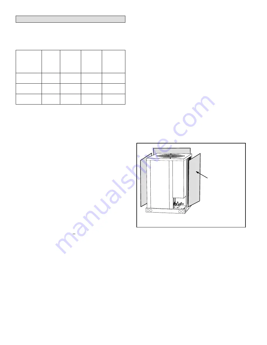
Outdoor Temp < 65ºF (18ºC)

1. When the outdoor ambient temperature is below 65F

(18C) it may be necessary to restrict the air flow
through the outdoor coil to achieve liquid pressures in
the 325-375 psig (2240-2585 kPa) range. These
higher pressures are necessary for checking the
charge. Block equal sections of the outdoor coil on all
coil sides until the liquid pressure is in the 325-375 psig
range (figure 4).

2. Charge the system as described in the approach

method section.

3. Switch to heating mode and let the system stabilize at

least 10 minutes. Then confirm that the pressures
obtained from the connected gauges match the
normal operating pressures (heating mode) in table 5

4. Minor variations in these pressures may be expected

due to differences in installations. Significant
differences could mean that the system is not properly
charged or that a problem exists with some
component in the system.

CARDBOARD OR
PLASTIC SHEET

OUTDOOR COIL SHOULD BE BLOCKED ONE SIDE AT A TIME
WITH CARDBOARD OR PLASTIC SHEET UNTIL PROPER
TESTING PRESSURES ARE REACHED.

Figure 4. Blocking Outdoor Coil

PROCEDURE — APPROACH METHOD

Use the following approach method along with the normal
operating pressures in cooling mode to confirm readings.

1. Using the same thermometer, compare liquid

temperature at service valve to outdoor ambient
temperature.

Approach Temperature = Liquid temperature

minus ambient temperature

2. Approach temperature should be as indicated in table

3 for each stage. An approach temperature greater
then this value indicates an undercharge. An approach
temperature less than this value indicates an
overcharge.

A

Add or remove charge in increments.

B

Allow the system to stabilize at least 5 minutes
each time refrigerant is added or removed

Содержание T-Class TPA090S4S

Страница 1: ...aller or equivalent or a service agency INSTALLATION INSTRUCTIONS T CLASSt TPA Series 7 5 AND 10 TON HEAT PUMPS 7 5 TO 10 TONS 506148 01 12 2015 Supersedes 10 2011 Table of Contents Shipping and Packing List 1 Outdoor Unit 1 Unit Dimensions Corner Weights and Center of Gravities 2 Unit Plumbing Parts Arrangement 3 Unit Control Box Components Arrangement 4 Model Number Identification 4 Rigging the ...

Страница 2: ...NG HOLES For Rigging FRONT VIEW TOP VIEW FORKLIFT SLOTS Both Sides SIDE VIEW 1108 48 3 4 1238 3 1 2 89 1149 FF EE INLET AIR INLETAIR B B AA CC DD CENTER OF GRAVITY ELECTRICAL INLETS Above Refrigerant Lines OUTDOOR FAN GUARDS INLETAIR BASE ELECTRICAL INLETS Above Refrigerant Lines OPTIONAL HAIL GUARD Field Installed All Coil Sides Not used with Coil Guard OPTIONAL HAIL GUARD Field Installed All Coi...

Страница 3: ...PRESSURE SWITCH S4 LOSS OF CHARGE SWITCH S24 CTXV SENSING BULB CHECK EXPANSIVE VALVE CTXV DEFROST SWITCH LOCATION S6 TPA120S4S LIQUID LINE BI FLOW DRIER LOSS OF CHARGE SWITCH S24 COMPRESSOR HIGH PRESSURE SWITCH S4 SUCTION LINE SERVICE VALVE LIQUID LINE SERVICE VALVE COIL REVERSING VALVE CTXV SENSING BULB CTXV SENSING BULB DEFROST SWITCH LOCATION S6 DEFROST SWITCH LOCATION S9 ...

Страница 4: ...n 3 3rd Revision Voltage Y 208 230V 3 phase 60hz G 460V 3 phase 60hz J 575V 3 phase 60hz Refrigerant Type 4 R 410A Refrigerant Circuits S Single Circuit Part Load Capability N Single Stage Compressor Rigging the Unit for Lifting Rig the unit for lifting by attaching four cables to the holes in the base rail of the unit as illustrated in figure 5 1 Remove protective packaging before rigging the uni...

Страница 5: ...efer to table 1 for field fabricated refrigerant line sizes for runs up to 50 linear feet 15 m Table 1 Refrigerant Line Sizes for Runs Up to 50 Linear Feet Unit Liquid Line Suction Line TPA 090 5 8 16 mm 1 3 8 35 mm TPA 120 5 8 16 mm 1 3 8 35 mm Refrigerant Line Limitations You may install the unit in applications that have line set lengths of up to 50 linear feet 15 m with refrigerant line sizes ...

Страница 6: ...ted by sunlight drafts or vibrations Install low voltage wiring from outdoor to indoor unit and from thermostat to indoor unit as illustrated THERMOSTAT 5 FEET 1 5M INSTALL THERMOSTAT TYPICAL CONTROL WIRING TPA HEAT PUMP C1 W1 C R C1 C RO TAA AIR HANDER Y1 C R A2 THERMOSTAT RT2 REMOTE SENSOR S2 S1 W2 W W2 W1 W2 3 4 NOTE FOR PROPER VOLTAGES SELECT THERMOSTAT WIRE CONTROL WIRES GAUGE PER TABLE ABOVE...

Страница 7: ...Page 7 TP SERIES Figure 3 TPA090S4S and TPA120S4S G J M and Y Voltages Typical Wiring Diagram ...

Страница 8: ...erences could mean that the system is not properly charged or that a problem exists with some component in the system 3 Switch to heating mode to confirm normal operating pressures Let the system stabilize at least 10 minutes then compare the pressure obtained from the connected gauges to the normal operating pressures heating mode in table 5 4 Verify the charge as described in the approach method...

Страница 9: ...18 C 231 128 243 130 239 132 239 132 75 F 24 C 265 130 281 133 289 135 289 135 85 F 29 C 310 131 325 136 322 137 322 137 95 F 35 C 358 134 372 139 370 140 370 140 105 F 41 C 410 137 427 140 422 142 422 142 115 F 46 C 467 140 478 142 480 145 480 145 125 F 52 C 551 146 548 142 541 148 541 148 Temperature of air entering outdoor Coil Table 5 HFC 410A Normal Operating Pressures Heating Mode Liquid 10 ...

Страница 10: ...130 475 6 146 579 8 38 113 6 54 152 8 69 197 3 85 254 1 100 317 2 116 396 0 131 481 6 147 586 8 39 115 8 55 155 5 70 200 6 86 258 0 101 321 8 117 401 3 132 487 8 148 593 8 40 118 0 56 158 2 71 203 9 87 262 0 102 326 4 118 406 7 133 494 0 149 601 0 41 120 3 57 161 0 72 207 2 88 266 0 103 331 0 119 412 2 134 500 2 150 608 1 42 122 6 58 163 9 73 210 6 89 270 0 104 335 7 120 417 7 135 506 5 151 615 4 ...

Страница 11: ... 90 T3 minutes The maximum defrost period is 14 minutes and cannot be adjusted NOTE Defrost control part number is listed near the P1 timing pins Units with defrost control 100269 02 The factory default defrost interval is 60 minutes Units with defrost control 100269 04 or higher The factory default defrost interval is 90 minutes If the timing selector jumper is missing the defrost control default...

Страница 12: ...r problem Simultaneous Slow Flash Normal operation Alternating Slow Flash 5 min anti short cycle delay Fault and Lockout Codes OFF Slow Flash Loss of Charge Fault OFF ON Loss of Charge Lockout Slow Flash OFF High Pressure Fault ON OFF High Pressure Lockout Maintenance At the beginning of each cooling season the system should be checked as follows OUTDOOR UNIT 1 Clean and inspect the condenser coil...

Страница 13: ...um Fuse or Circuit Breaker Electrical Connections Tight Indoor Filter clean Supply Voltage Unit Off Indoor Blower RPM S P Drop Over Indoor Dry Outdoor Coil Entering Air Temp Vapor Pressure Refrigerant Lines Leak Checked Properly Insulated Outdoor Fan Checked Service Valves Fully Opened Caps Tight Voltage With Compressor Operating SEQUENCE OF OPERATION Calibrated THERMOSTAT Properly Set Level Heati...

Отзывы: