V
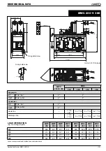
Q
Dt
MWC
180
4
645
230
5
659
280
6
669
330
5
946
380
4
1362
450
6
1075
510
6
1218
570
6
1362
650
6
1553
720
6
1720
+ 5°C
►
0°C
10%
1,05
1,02
0,99
0,994
0°C
►
-5°C
20%
1,10
1,05
0,98
0,993
- 5°C
►
-10°C
30%
1,15
1,08
0,97
0,99
- 10°C
►
-15°C
35%
1,18
1,10
0,96
0,987
Application Guide
•
MWC-0410-E
• 11 •
HYDRAULIC DATA
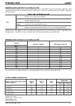
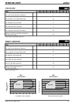
Vmini = 86 x Q / (Nstages x Dt)
Where :
Minimum water content of the installation
Cooling capacity of the chiller
Nstage
Number of control steps available in the unit
Maximum acceptable temperature rise (Dt = 6°c for an air conditioning application)
Important note: In case MWC™ is used in air-conditioning applications with a short water system (e.g. MWC™ application with air
handling units) or in case MWC™ is used for industrial process cooling, it is mandatory to use a buffer tank.
MINIMUM WATER CONTENT OF AN INSTALLATION
Thanks to multi step capacity control and smart anti-short compressor cycling, MWC™ can work with minimum water loop volume
as de
fi
ned here below. This can eliminate the need for a buffer tank in most of air-conditioning applications (e.g. MWC™ application
with fan-coil units). :
Unit Size
Number of stages
Mini water volume (l)
MINIMUM WATER CONTENT OF AN INSTALLATION
GLYCOL CORRECTION FACTOR
Example : 10% glycol
Minimum
fl
ow : 1,19 m
3
/h x 1,02
Pressure drop x 1,07
System capacity x 0,99
Minimum ambient temperature or water
outlet temperature
Ethylene
glycol
Pressure
drop
Water
fl
ow
CAPACITIES
Cooling
Heating
Note : The volume of the condenser water loop has no impact on the chiller operation. In heat pump operation (with hot water set point control option)
the minimum volume of the condenser water loop must be calculated based on the heating capacity using the same formula.


