Page 8
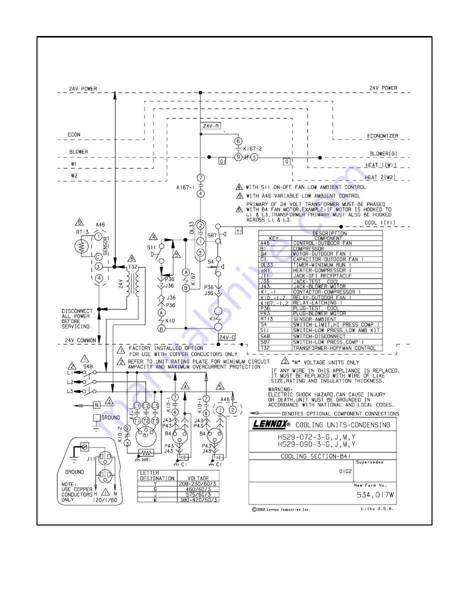
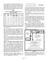
Typical Unit Wiring Diagram
HS29−072, 090
Figure 8
Страница 1: ...ting 7 Electrical 7 Plumbing 10 Service Valves 17 Leak Testing 18 Evacuation Dehydration 18 Start Up 19 Charging 20 System Operation 21 Maintenance 21 Start Up Performance Check List 22 Shipping Packi...
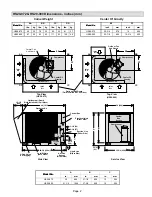
Страница 2: ...et Air Inlet Air AA BB CC DD Center Of Gravity EE FF AA BB CC DD Center Of Gravity EE FF Compressor A 3 1 4 83 34 864 B Control Box Access Side View Lifting Holes For Rigging Forklift Slots Both Sides...
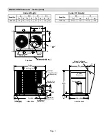
Страница 3: ...l Outdoor Fans And Guards 2 Control Box Lifting Holes For Rigging Forklift SlotS Both Sides Discharge Air Inlet Air Electrical Inlets Either Side Liquid Line Either Side 1 7 16 37 6 5 8 168 4 3 8 111...
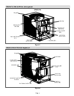
Страница 4: ...lve low pressure switch S87 low ambient switch S11 fan guard compressor B1 liquid line service valve HS29 120 Unit Parts Arrangement Figure 2 condenser fan motor B4 B5 control box low ambient switch S...
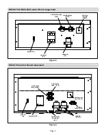
Страница 5: ...C1 minimum run timer DL33 outdoor fan relay K10 latching relay K167 ground lug HS29 120 Control Box Arrangement Figure 4 contactor K1 low ambient thermostat S41 capacitor C1 C2 latching relay K167 ou...
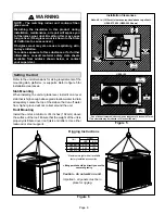
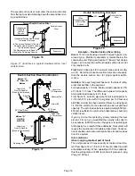
Страница 6: ...ve grade to allow water to drain adequately Locate the top of the slab so that run off water from higher ground will not collect around the unit Roof Mounting Install the unit at a minimum of 4 inches...
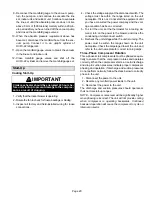
Страница 7: ...y and maximum overcurrent protection size WARNING Unit must be grounded in accordance with national and local codes Electric Shock Hazard Can cause injury or death Line Voltage Knockouts are provided...
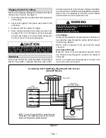
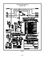
Страница 8: ...Page 8 Typical Unit Wiring Diagram HS29 072 090 Figure 8...
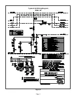
Страница 9: ...Page 9 Typical Unit Wiring Diagram HS29 120 Figure 9...
Страница 10: ...elihood of slugging is greatly increased if the lines are over 50 feet 15 m An incremental increase in liquid line size results in a 40 to 50 percent increase in liquid refriger ant to fill the line T...
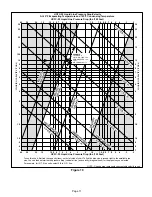
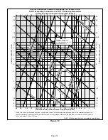
Страница 11: ...2 1 5 1 0 9 8 7 6 5 4 3 2 HCFC 22 Liquid Line Pressure Drop lbs 100 Feet NOTE Shaded area represents unacceptable velocity range Figure 10 12 5 40 30 20 15 40 30 20 15 EXAMPLE 10 TON UNIT 5 8 IN O D...
Страница 12: ...e drop due to friction and the pressure drop due to vertical lift then add the two Pressure drop due to friction Pressure drop due to vertical lift Pressure drop in the liquid line You must consider t...
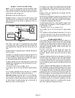
Страница 13: ...00 fpm velocity for oil entrainment In order to ensure oil entrainment suction risers require a mini mum velocity of 1200 fpm 1500 fpm is preferred re gardless of the length of the riser Figure 14 ill...
Страница 14: ...0 9 8 7 6 5 4 3 2 1 5 1 0 9 8 7 6 5 4 3 2 HCFC 22 Suction Line Pressure Drop lbs 100 Feet NOTE Shaded area denotes unacceptable velocity range Figure 14 40 30 20 15 40 30 20 15 EXAMPLE 10 TON UNIT 1 3...
Страница 15: ...ss of 1 8 psig Use figure 14 to calculate the pressure drop in 25 feet of 1 3 8 inch line Multiply 2 100 by 25 feet to calculate friction loss of 0 5 psig This loss has already been included in the ca...
Страница 16: ...ells Find Select tube sizes for horizontal runs and risers fig ure 14 Determine if double suction risers are necessary Size the double suction riser for proper system perfor mance Solution Size each s...
Страница 17: ...psig The total pressure drop for the riser is equal to the average of the pressure drop in both risers 1 4 B riser drop 1 26 A riser drop 2 66 2 66 2 1 33 average pressure drop through A and B risers...
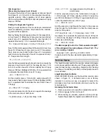
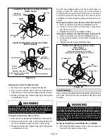
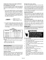
Страница 18: ...Schrader valve core is present in this valve A cap is also provided to seal off the service port The valve is not re buildable so it must always be replaced if failure has oc curred Opening the Suctio...
Страница 19: ...the manifold gauge set to the service valve ports as follows D low pressure gauge to suction line service valve D high pressure gauge to liquid line service valve 3 Purge the system of dry air helium...
Страница 20: ...isted on the unit nameplate If it is not do not start the equipment until you have consulted the power company and the volt age condition has been corrected 5 To start the unit set the thermostat for...
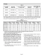
Страница 21: ...1 105_F 40_C 298 71 308 82 314 77 290 73 115_F 46_C 333 72 342 83 352 79 328 74 HS29 072 tested with CB30U 65 Pressure shown is with typical 5 ton indoor coil match up HS29 072 and HS29 090 tested wit...
Страница 22: ...time control This control prevents the compressor from short cycling and ensures that the oil returns to the compressor properly When a cooling cycle begins the run time control keeps the compressor o...
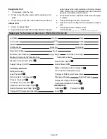
Страница 23: ...al ____________ Start Up Performance Check List HS29 072 090 120 Job Name Job Location Installer Unit Model No Nameplate Voltage Minimum Circuit Ampacity Maximum Overcurrent Protection Size Refrigeran...